


Model 5601MSC
Model 5601MSC Master SPG/Master Clock System
Page - 6
Revision 2.2
OVERVIEW
1.1.6. Checking the Status of the Unit
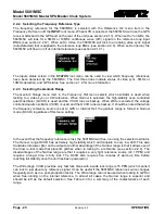
After the input references are connected and set up, the status of the unit can be checked by pressing
the STATUS button on the front panel. There are several different status screens which can be selected
by using the control knob or the
and
buttons. The status of the frequency and time references can
be viewed by choosing the Lock status screen and pressing SELECT. Press ESC to return to the status
menu to select another screen for viewing. Any screen name that is highlighted with a red or yellow
background indicates that one of the statuses in that screen is in a fault or warning condition.
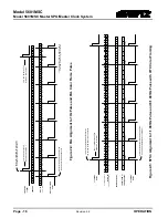
Figure 1-3: Rear View of 5601MSC
1.1.7. Wiring the Outputs
Most outputs are provided as BNC connectors and wiring is straightforward. There are also two male
XLR connectors for the two primary LTC/IRIG outputs. The LTC/IRIG input and secondary copies of
LTC1 and LTC2 are available on the 15-pin D-sub
GPIO
connector. This connector also has two GPIs
(general purpose inputs) and two GPOs (general purpose outputs). The cable for this connector is not
supplied and must be built by the end user.
If a test generator option is installed, such as the
SDTG
,
HDTG
, or
3GTG
options, there will be two
channels of balanced analog audio and balanced versions of the AES1, AES2, and DARS outputs
available on a 16-pin removable terminal block connector. The removable terminal block can be
unscrewed from the 5601MSC to be wired up, then inserted and secured with the two slotted flange
screws. The terminal block can accept wires in the range of 28-18 AWG. Stranded wires should be
tinned first or crimped to wire pin terminals. The tension clamp can be released by pushing a small
slotted screwdriver into the middle square hole. The wire can then be inserted into the outside round
hole and then clamped by removing the screwdriver.
If the 5601MSC is to be used as part of a dual redundant system involving a 5601ACO2 automatic
changeover, the wiring diagram in section 1 should be observed. Use the 15-pin male-male cables
included with the 5601ACO2 to connect the GPIO ports of the 5601MSCs to the 5601ACO2. The SNSA
and SNSB pins can be used by the 5601MSC to detect the 5601ACO2 and automatically enable
highdrive on the SDI TG outputs. If automatic highdrive support is not required, these pins may be left
unconnected but highdrive will have to be enabled manually for the SDI TGs. The GPI and LTC input
connections on the 5601ACO2 are internally split and sent to both 5601MSC units.
Содержание 5601MSC
Страница 2: ...This page left intentionally blank ...