background image

3405 Frame Manual 

3405FR-BNC Fiber Optic SFP Frame  


Revision 2.3 


REVISION HISTORY 


REVISION 

DESCRIPTION 

DATE


1.0 

First Release 

Mar 2009 

 
1.1 

Added Status LED and VistaLINK Monitoring description 

Mar 2009 

 
1.2 

Added power supply cabling information 

Jun 2009 

 
1.3 

Added SFP variants and VLPRO screenshots & parameter chart 

Nov 2009 

  
1.4 

Removed Status LED note in section 6.2.1 

Dec 2009 

 
1.5 

Revised front and rear panel screens and added Ethernet configuration 

Apr 2010 

 
1.6 

Added information regarding the 3405FAN-Q module 

Jun 2010 

 
1.7 

Revised serial port command and VistaLINK parameters 

Sept 2010 

 
1.8 

Added 3405 Series CWDM Passive Optical Modules section  

Oct 2010 

 
2.0 

3405 Series Manual – merged all 3405FR frame information 

Nov 2010 

 
2.1 

Added 48V versions, updated specifications 

Dec 2010 

 
2.2 

Modified 3405PST LED functionality 

Feb 2011 

 
2.3 

Added requirements for NEBS documentation 

May 2013 


Information contained in this manual is believed to be accurate and reliable. However, Evertz assumes no responsibility for the use thereof or for 
the rights of third parties, which may be effected in any way by the use thereof.  Any representations in this document concerning performance of 
Evertz products are for informational use only and are not warranties of future performance, either expressed or implied.  The only warranty 
offered by Evertz in relation to this product is the Evertz standard limited warranty, stated in the sales contract or order confirmation form. 
 
Although every attempt has been made to accurately describe the features, installation and operation of this product in this manual, no warranty 
is granted nor liability assumed in relation to any errors or omissions unless specifically undertaken in the Evertz sales contract or order 
confirmation.  Information contained in this manual is periodically updated and changes will be incorporated into subsequent editions.  If you 
encounter an error, please notify Evertz Customer Service department. Evertz reserves the right, without notice or liability, to make changes in 
equipment design or specifications.


Содержание 3405FR Series

Страница 1: ... evertz com Version 2 3 May 2013 The material contained in this manual consists of information that is the property of Evertz Microsystems and is intended solely for the use of purchasers of the 3405FR Series Evertz Microsystems expressly prohibits the use of this manual for any purpose other than the operation of the device All rights reserved No part of this publication may be reproduced without...

Страница 2: ...ird grounding prong The wide blade or the third prong are provided for your safety If the provided plug does not fit into your outlet consult an electrician for replacement of the obsolete outlet Protect the power cord from being walked on or pinched particularly at plugs convenience receptacles and the point where they exit from the apparatus Only use attachments accessories specified by the manu...

Страница 3: ...ation for handling fiber optics WARNING CAUTION CLASS 1 VISIBLE INVISIBLE LASER RADIATION WHEN OPEN DO NOT VIEW DIRECTLY OR WITH OPTICAL INSTRUMENTS ELECTROSTATIC SENSITIVE DEVICES The hand symbol within an equilateral triangle is intended to alert the user to instructions related to precautions for handling electrostatic sensitive devices See Electro Static Discharge ESD Precautions section for f...

Страница 4: ...on of Primary Protectors is not sufficient protection in order to connect these interfaces metallically to OSP wiring The intra building port s of the equipment or subassembly must use shielded intra building cabling wiring that is grounded at both ends This equipment is to be connected to a Common Bonding Network See Installation section for further information This equipment is to be installed i...

Страница 5: ...o comply with the limits for a Class A digital device pursuant to Part 15 of the FCC Rules These limits are designed to provide reasonable protection against harmful interference when the equipment is operated in a commercial environment This equipment generates uses and can radiate radio frequency energy and if not installed and used in accordance with the instruction manual may cause harmful int...

Страница 6: ...elieved to be accurate and reliable However Evertz assumes no responsibility for the use thereof or for the rights of third parties which may be effected in any way by the use thereof Any representations in this document concerning performance of Evertz products are for informational use only and are not warranties of future performance either expressed or implied The only warranty offered by Ever...

Страница 7: ... HANDLING OF OPTICAL FIBER 13 2 4 1 Safety 13 2 4 2 Assembly 13 2 4 3 Labeling 14 2 4 4 Handling and Connecting Fibers 14 2 5 FIBER INPUT AND OUTPUT CONNECTIONS 15 2 5 1 Electro Static Discharge ESD Precautions 16 2 5 2 3405FR BNC SFP Module Variants 16 2 5 3 3405FR DIN SFP Module Variants 17 2 5 4 3405FR XLINK SFP Module Variants 18 2 5 5 Installing an SFP Module 18 2 5 6 Removing an SFP Module 1...

Страница 8: ... 12 3405PSX EXTERNAL POWER SUPPLY BRICK 26 3 13 3405PS 6 1RU POWER SUPPLY TRAY 26 3 14 COMPLIANCE 27 4 STATUS AND LEDS 28 4 1 1 STATUS LED 28 4 1 2 SFP Monitoring LEDs 28 5 CONFIGURATION AND CONTROL 30 5 1 3405 FRAME CONTROLLER CONFIGURATION 30 5 2 VISTALINK CONFIGURATION 32 5 2 1 General Tab 32 5 2 2 TX RX Configuration Tabs 34 5 2 2 1 Tx Configuration 36 5 2 2 2 Rx Configuration 36 5 2 3 Faults ...

Страница 9: ...Tray 8 Figure 2 7 3405PSX Power Supply 9 Figure 2 8 Locating the External 48V DC Power Connector 10 Figure 2 9 3405PST Status Indicators 11 Figure 2 10 Front View of 3405FAN 12 Figure 2 11 Cooling Fan Installation and Removal 13 Figure 2 12 Reproduction of Laser Certification and Identification Label 14 Figure 2 13 3405FR Front View with Fiber Inputs and Outputs 15 Figure 2 14 3405T 3405R 3405T13 ...

Страница 10: ...aLINK Network Parameter Tab 39 Figure 5 17 3405FC VistaLINK Trap Destination Tab 40 Figure 5 18 3405FC VistaLINK FC Faults Tab 40 Figure 7 1 3405CWDM M8 Simplified Block Diagram 45 Figure 7 2 3405CWDM M16 Simplified Block Diagram 45 Figure 7 3 3405CWDM 2 M16 Simplified Block Diagram 46 Figure 7 4 3405CWDM 2 M8 Simplified Block Diagram 47 Figure 7 5 8 Channel Breakout Cable 48 Figure 7 6 Wiring Dia...

Страница 11: ...p to 32 EO OE or mixture of EO and OE in a 1RU unit 3405FR XLINK Fiber Optic SFP X LINK Frame X LINK Up to 32 EO or 32 OE X LINK conversions in a 1RU unit 3405FR BNC 48V Fiber Optic SFP BNC Frame with Dual 48V DC Inlets BNC Up to 32 EO OE or mixture of EO and OE in a 1RU unit 3405FR DIN 48V Fiber Optic SFP DIN Frame with Dual 48V DC Inlets miniDIN Up to 32 EO OE or mixture of EO and OE in a 1RU un...

Страница 12: ...l RX SFP Evertz Dual TX SFP Serial IN Evertz Dual TX SFP Evertz Dual TX SFP Optical OUT Optical OUT 3405FC Primary Frame Controller TOP TRAY RJ 45 Local Fault Indication 3405FC 2 Optional Secondary Frame Controller BOTTOM TRAY RJ 45 Local Fault Indication 3405PT Power Tray 1 3405PT Power Tray 2 Optical IN Optical IN Optical IN Optical IN Serial OUT Serial OUT Serial OUT Serial OUT Serial OUT Seria...

Страница 13: ... Indication 3405PT Power Tray 1 3405PT Power Tray 2 Optical I O Serial I O SFP s 1 16 DB9 3405FAN Dual Fan Module FLOW FLOW 3405PS 6 1RU Power Tray 3405PSX Brick 3405PSX Brick 12V 12V 110 220V AC 110 220V AC Serial I O Serial I O Optical I O Evertz SFP Optical I O Optical I O Optical I O Optical I O Serial I O Serial I O Serial I O 16 or 32 channel CWDM MUX DEMUX Optical Mux Demux 1 2 Common 3405C...

Страница 14: ...Y RJ 45 Local Fault Indication 3405FC 2 Optional Secondary Frame Controller BOTTOM TRAY RJ 45 Local Fault Indication 3405PT Power Tray 1 3405PT Power Tray 2 Optical I O SFP s 1 16 DB9 3405FAN Dual Fan Module FLOW FLOW 3405PS 6 1RU Power Tray 3405PSX Brick 3405PSX Brick 12V 12V 110 220V AC 110 220V AC Optical I O Evertz SFP Optical I O Optical I O Optical I O Optical I O X LINK I O X LINK BUS Figur...

Страница 15: ...he 3405FR Series frames require 1 rack unit i e 1 75 inches 45 mm of standard 19 inch 483 mm wide rack space To firmly fasten the frame to the equipment rack make sure that all four mounting screws are securely tightened Figure 2 1 External Views of 3405FR BNC Figure 2 2 External Views of 3405FR DIN ...

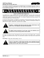
Страница 16: ...necting power to the 48VDC versions see section 2 2 The 3405FR series frames require a nominal 12 Volt DC power source Optionally you can connect one of two different external AC to DC power supply converters 3405PSX or 3405PS 6 12 Volt DC power should be applied to the 3405FR by connecting a 4 PIN XLR power supply cord to the main power entry inlet on the rear panel 12V DC IN 1 CAUTION MAKE SURE ...

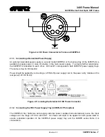
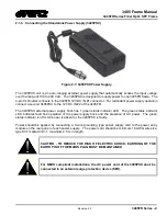
Страница 17: ...nlet 1 corresponds to both 3405PST power supply trays The same is true for DC inlet 2 Power should be applied by connecting a 4 PIN XLR power supply cord to the power entry module on the rear panel 12V DC IN 2 Figure 2 5 Locating the External 12V DC Power Connector 2 1 2 Connecting the 1RU Power Supply Tray 3405PS 6 PS 6 option The 3405PS 6 tray holds two auto ranging external power supplies that ...

Страница 18: ...ng LEDs green and red will be off AC Power should be applied to the 3405PS 6 by connecting a 3 wire grounding type power supply cord to the power entry module on the rear panel of each power supply The power cord should be minimum 18 AWG wire size type SVT marked VW 1 maximum 2 5 m in length CAUTION TO REDUCE THE RISK OF ELECTRIC SHOCK EARTHING OF THE EARTH PIN OF THE MAINS PLUGS MUST BE MAINTAINE...

Страница 19: ...X external power supply brick has 1 green status indicator LED The green status indicator LED indicates fault free operation of the power supply brick and the presence of AC power The green status indicator is off is AC power is absent or the 3405PSX is faulty Power should be applied by connecting a 3 wire grounding type power supply cord to the power entry module on the rear panel of each power s...

Страница 20: ...an isolated DC return also known as a DC I configuration Figure 2 8 Locating the External 48V DC Power Connector CAUTION TO REDUCE THE RISK OF ELECTRIC SHOCK EARTHING OF THE EARTH PIN DC INPUT TERMINAL STRIP MUST BE MAINTAINED If there is a fuse failure contact Evertz customer service regarding the power supply immediately The power supplies are short circuit protected and should not blow the fuse...

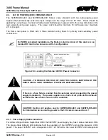
Страница 21: ... 2009 the 3405PST power supply tray has 2 status indicator LEDs The green status indicator LED indicates fault free operation of the PST unit The red status indicator LED indicates a faulty 3405PST unit Figure 2 9 3405PST Status Indicators 2 3 GROUNDING AND BONDING NEBS APPLICATIONS The NEBS compliant version of this equipment is to be connected to a Common Bonding Network 1 1 2 2 2 3 2 Figure 2 1...

Страница 22: ...ipment as shown in Figure 2 10 The ground lug must be secured as shown using four star washers to prevent anti rotation of the nuts and two M4 nuts Tighten the nuts securely to provide a good bonding connection 2 4 FAN INSTALLATION AND REMOVAL 3405FAN Figure 2 11 provides an illustration of the 3405FAN front view Figure 2 11 Front View of 3405FAN 2 4 1 Cooling The 3405FR frame is designed to ensur...

Страница 23: ...FR Undo the captive screw and pull outwards on the metal tab at the bottom of the 3405FAN Installation is the reverse of removal CAUTION To achieve adequate cooling care should be taken to ensure that the fan inlets and exhaust openings are free of obstructions 2 5 CARE AND HANDLING OF OPTICAL FIBER 2 5 1 Safety CLASS 1 LASER PRODUCT Background colour yellow Triangular band black Symbol black 2 5 ...

Страница 24: ...ction of Laser Certification and Identification Label 2 5 4 Handling and Connecting Fibers Never touch the end face of an optical fiber Always keep dust caps on optical fiber connectors when not connected and always remember to properly clean the optical end face of a connector before making a connection The transmission characteristics of the fiber are dependent on the shape of the optical core a...

Страница 25: ...ront of the 3405FR frame correspond to channels A and B on the rear of the frame Figure 2 16 Figure 2 15 depicts any one of the following Evertz SFP modules 3405T13 2 3405Txx yy 2 3405R 2 3405R 2R 3405OO13 DA4 and 3405OOxx DA4 Figure 2 15 3405T 3405R 3405T13 R and 3405OO13 DA4 Evertz SFP Modules The SFP fiber modules are equipped with a class 1 laser and emit invisible radiation Avoid exposure to ...

Страница 26: ...l strap to discharge the static voltage from your body 2 Use a Safe Work Area Avoid handling modules in areas that have a floor or work surface covering capable of generating a static charge Also nothing capable of generating or holding a static charge should be allowed in the work area 3 Handle ESD sensitive modules carefully Do not slide modules over any surface Do not touch exposed connector pi...

Страница 27: ...3405 Frame Manual 3405FR Series Fiber Optic SFP Frame Revision 2 3 3405FR Series 17 2 6 3 3405FR DIN SFP Module Variants ...

Страница 28: ...g a new SFP module 1 Remove the SFP module from its protective packaging You can identify if your particular SFP module is a duplex transmitter or duplex receiver Observe the top of the SFP module The part number is located on the top of the SFP module A 3405T 2 part number denotes a duplex transmitter module output and a 3405R 2 denotes a duplex receiver module input A 3405T13 R part number denot...

Страница 29: ... or the optical interfaces in the SFP module Disconnect all cables before removing or installing SFP modules 1 Pull the bale clasp latch out and down to eject the module If the latch is obstructed and you are not able to release the clasp use a small flat blade screwdriver or other narrow flat instrument to open the bale clasp latch 2 Grasp the SFP module between your thumb and index finger and ca...

Страница 30: ...annels A and B on the front of the 3405FR DIN frame Figure 2 14 correspond to channels A and B on the rear of the frame 2 7 3 Rear Panel XLINK Connections The X LINK IO s on the rear of the 3405FR XLINK are fixed and correspond to a particular SFP module This X LINK connector is agile and thus configured as inputs or outputs An X LINK connector will become an electrical input if its corresponding ...

Страница 31: ...A 5 15 A 6 7 B 7 15 B 8 7 A 9 14 A 10 6 B 11 14 B 12 6 A 13 13 A 14 5 B 15 13 B 16 5 A 17 12 A 18 4 B 19 12 B 20 4 A 21 11 A 22 3 B 23 11 B 24 3 A 25 10 A 26 2 B 27 10 B 28 2 A 29 9 A 30 1 B 31 9 B 32 1 A 2 7 4 3405FR BNC 48V and 3405FR DIN 48V Rear Panels Figure 2 19 3405FR BNC 48V Rear Panel Figure 2 20 3405FR DIN 48V Rear Panel ...

Страница 32: ...dant supply Each power supply is capable of supplying full power to up to 6 3405FR series frames by itself however we recommend running with both supplies powered for power redundancy The left and right power supplies are identical If the Power supply is removed with the power cord still connected to the mains there is a potential shock hazard present as there will be mains voltages present on the...

Страница 33: ...it condition The fuse holders are located on the front of the power tray To change the fuse for one of the supplies you should first disconnect the power cord for the power supply Insert a flat blade screwdriver in the fuse holder and turn clockwise Pull out the fuse from the fuse holder using a small screwdriver Remove the blown fuse and replace with a fuse of the correct value The correct fuse r...

Страница 34: ... 0 2 3 Female connector 3 3 3405FR XLINK FRAME Density Up to 32 EO OE or mixture of EO and OE to X LINK conversion in a 1RU unit Impedance 75Ω Connector XLINK 3 4 COMMUNICATION AND CONTROL Serial RS 232 single Female 9 pin D connector Ethernet SNMP over IEEE 802 3 U 10 100 BaseTx RJ 45 connector Control VistaLINK 3 5 OPTICAL OUTPUT Number of Outputs 3405FR BNC Up to 2 per SFP 3405FR DIN Up to 2 pe...

Страница 35: ...292M 1 5Gb s SMPTE 259M 270Mb s DVB ASI Connector 3405FR BNC BNC per IEC 61169 8 Annex A 3405FR DIN DIN 1 0 2 3 Female connector Equalization Automatic to 80m 3Gb s 100m 1 5Gb s 250m 270Mb s with Belden 1694A or equivalent Return Loss 15dB up to 1 5GHz 10dB up to 3GHz 3 8 ELECTRICAL OUTPUTS 3405FR BNC 3405FR DIN ONLY NOTE Electrical outputs specs only apply to reclocking SFP modules 3405T13 R 3405...

Страница 36: ...uration Dual External Supplies primary secondary Voltage Auto ranging 36 72V DC Maximum Power Consumption 50W Typical fully loaded frame with all accessories Note Power consumption dependent on SFP type Connectors 3 pin screw terminal strip 1 per power supply Status Indicators PST status LEDs each per power supply tray 3 12 3405PSX EXTERNAL POWER SUPPLY BRICK AC Mains Input Auto ranging 100 240 VA...

Страница 37: ...m 11 Complies with CE Low voltage Directive 2004 108 EC Laser Safety Class 1 laser product Complies with 21 CFR 1040 10 and 1040 11 except for deviations pursuant to Laser Notice No 50 dated June 24 2007 Complies with IEC 60825 1 2007 Edition 2 EMC Complies with FCC part 15 class A Complies with EU EMC directive 2006 95 EC ROHS Complies with EU restriction on hazardous substances 2002 95 EC ...

Страница 38: ...es are all functioning normally Table 4 1 Status LED Chart 4 1 2 SFP Monitoring LEDs The 16 LEDs on the front of the 3405FC signify SFP module presence and signal status 1 through 16 LED Description No LED An unlit LED indicates that there is no SFP plugged into the associated port number Red LED Red LEDs indicate the presence of an error with the particular SFP inserted in the corresponding port ...

Страница 39: ...e Revision 2 3 3405FR Series 29 A backup 3405FC frame controller module can optionally be installed in the frame in the same manner as the primary 3405FC Figure 4 2 Front of 3405FC 2 Note The Redundancy of the frame controller is currently not supported ...

Страница 40: ... none d Stop Bits 2 e Flow Control none 3 Power on the 3405FR unit 4 From the main menu two selections are available S 3405 Menu Engine V0 1 1 3405 Controller Settings 2 TX RX SFP Modules Settings 5 Under menu item 1 3405 Controller Settings the following items are available S 3405 Menu Engine V0 1 1 View Network Settings Displays current network settings 2 Change IP Address Enter new IP Address 3...

Страница 41: ...put inversion mode of channels 1 and or 2 under SFP RX Settings 6 Set RX SD HD Set output slew rate of channels 1 and or 2 under SFP RX Settings 3405R 2R 1 Display SFP Status Displays SFP status parameters under SFP Module Settings 2 Display SFP Serial Number Displays SFP serial number under SFP Module Settings 3 Display SFP Error Message Displays SFP error message under SFP Module Settings 4 Set ...

Страница 42: ...to 5 2 3 illustrate VistaLINK parameters for the following SFP types 3405T13 2 3405T13 R 3405R 2 3405R 2R and 3405OO13 DA4 5 2 1 General Tab The General tab enables the user to view the status of various parameters such as SFP Type Serial Number and SFP Firmware Version Figure 5 1 3405T13 2 VistaLINK General Tab Figure 5 2 3405T13 R VistaLINK General Tab ...

Страница 43: ... 2 3 3405FR Series 33 Figure 5 3 3405OO13 DA4 VistaLINK General Tab Figure 5 4 3405R 2 VistaLINK General Tab Figure 5 5 3405R 2R VistaLINK General Tab SFP Type Displays the type of SFP plugged into a particular slot SFP Serial Number Displays the SFP serial number ...

Страница 44: ...t Laser Status Wavelength SFP Status and Reclocker Status It also allows the user to set Squelch mode The RX Configuration tab displays the Received Optical Power and Reclocker Status It also allows the user to set Optical Input Power Threshold Inversion mode Slew Rate mode Squelch Mode and Swap Channel mode Figure 5 6 3405T13 2 VistaLINK TX Configuration Tab Figure 5 7 3405T13 R VistaLINK TX Conf...

Страница 45: ...3405 Frame Manual 3405FR Series Fiber Optic SFP Frame Revision 2 3 3405FR Series 35 Figure 5 8 3405OO13 DA4 VistaLINK RX Configuration Tab Figure 5 9 3405R 2 VistaLINK RX Configuration Tab ...

Страница 46: ...eclocker Displays Reclocking Standard if applicable Low Optical Threshold Sets Low Optical Threshold value Inversion Sets output inversion mode Slew Feature Sets output Slew rate mode Squelch Sets output squelch mode Swap Channel Sets output mapping mode 5 2 3 Faults Tab The Faults tab allows the user to enable a variety of traps To enable a particular trap simply click the box adjacent to each tr...

Страница 47: ...3405 Frame Manual 3405FR Series Fiber Optic SFP Frame Revision 2 3 3405FR Series 37 Figure 5 11 3405T13 2 VistaLINK Faults Tab Figure 5 12 3405T13 R VistaLINK Faults Tab ...

Страница 48: ...3405 Frame Manual 3405FR Series Fiber Optic SFP Frame 3405FR Series 38 Revision 2 3 Figure 5 13 3405OO13 DA4 VistaLINK Faults Tab Figure 5 14 3405R 2 VistaLINK Faults Tab ...

Страница 49: ... 2 6 illustrate VistaLINK parameters for the 3405FC Frame Controller 5 2 4 Network Parameters Tab The Network parameter tab enables the user to define the network parameters of the 3405FC IP Address Subnet Mask Gateway Address and Broadcast Address can be modified Under this tab there is also an option to reboot the frame Figure 5 16 3405FC VistaLINK Network Parameter Tab ...

Страница 50: ...roadcast to the VistaLINK SNMP Client and can be viewed in the trap log 5 2 6 FC Faults Tab The FC Faults tab allows the user to enable a variety of traps To enable a particular trap simply click the box located beside each trap so that a check mark appears When a check mark is present the trap is enabled When a check mark is not present the trap is disabled The Trap Status section defines whether...

Страница 51: ...rk from a central station and receive feedback that the configuration has been carried out An SNMP manager also known as a Network Management System NMS is a computer running special software that communicates with the devices in the network Evertz VistaLINK Pro Manager graphical user interface GUI third party or custom manager software may be used to monitor and control Evertz VistaLINK enabled p...

Страница 52: ...ealth SFP Communication Loss Monitors SFP communication with frame controller Fan 1 Bad Monitors health of fan 1 of 3405FAN unit Fan 2 Bad Monitors health of fan 2 of 3405FAN unit PSU 1 Fail Monitors health of upper 3405PST unit PSU 2 Fail Monitors health of lower 3405PST unit External Power 1 Fail Monitors the presence of AC power to DC inlet 1 External Power 1 Fail Monitors the presence of AC po...

Страница 53: ...05FR Series Fiber Optic SFP Frame Revision 2 3 3405FR Series 43 Squelch Sets the Output Squelch mode Swap Channel Sets the Channel Swap mode Slew Feature Sets the Output Slew rate Table 6 3 VistaLINK Controlled Parameters ...

Страница 54: ...of each of 1470nm to 1610nm onto two separate fibers 3405CWDM 2 D8 Dual 8 Channel Demux Separates two of each of 1470nm to 1610nm from two separate fibers 3405CWDM M8 8 Channel Mux Combines 1470nm to 1610nm onto one separate fiber 3405CWDM D8 8 Channel Demux Separates 1470nm to 1610nm from one separate fiber Table 7 1 Passive Optical Modules 7 1 1 3405CWDM Coarse Wavelength Division Multiplexor Th...

Страница 55: ...ot swappable from front of frame with minimal fiber disconnect reconnect LC PC connector option Fiber protector to prevent connector damage 1470 1490 1510 1530 1550 1570 1590 1610 1470 1490 1510 1530 1550 1570 1590 1610 Combined 1470 to 1610nm Figure 7 1 3405CWDM M8 Simplified Block Diagram 1270 1290 1310 1330 1350 1370 1430 1450 1470 1490 1510 1530 1550 1570 1590 1610 1270 1290 1310 1330 1350 137...

Страница 56: ...90 1610 1270 1290 1310 1330 1350 1370 1430 1450 1470 1490 1510 1530 1550 1570 1590 1610 1270 1290 1310 1330 1350 1370 1430 1450 1470 1490 1510 1530 1550 1570 1590 1610 1270 1290 1310 1330 1350 1370 1430 1450 1470 1490 1510 1530 1550 1570 1590 1610 Combined 1270 to 1610nm Set 1 Combined 1270 to 1610nm Set 2 Figure 7 3 3405CWDM 2 M16 Simplified Block Diagram ...

Страница 57: ...ries 47 1470 1490 1510 1530 1550 1570 1590 1610 1470 1490 1510 1530 1550 1570 1590 1610 1470 1490 1510 1530 1550 1570 1590 1610 1470 1490 1510 1530 1550 1570 1590 1610 Combined 1470 to 1610nm Set 1 Combined 1470 to 1610nm Set 2 Figure 7 4 3405CWDM 2 M8 Simplified Block Diagram ...

Страница 58: ...els include the following wavelengths 1270nm 1290nm 1310nm 1330nm 1350nm 1370nm 1430nm 1450nm The HI band channels include the following wavelengths 1470nm 1490nm 1510nm 1530nm 1550nm 1570nm 1590nm 1610nm Connection from output lasers of the 3405FR SFP s to the input of the Mux requires a series of LC to MTP break out cables Figure 7 5 8 Channel Breakout Cable The LO band break out cable is for us...

Страница 59: ...1 X LO 1 X HI 3405CWDM D16 16 Channel Demux 1 X LO 1 X HI 3405CWDM 2 M8 Dual 8 Channel Mux 2 X HI 3405CWDM 2 D8 Dual 8 Channel Demux 2 X HI 3405CWDM M8 8 Channel Mux 1 X HI 3405CWDM D8 8 Channel Demux 1 X HI Table 7 2 3405CWDM Model and The Associated Required Fanout Cable Note For LO breakout cable use Evertz Part number CB MTP40CM LCPC LB For HI breakout cable use Evertz Part number CB MTP40CM L...

Страница 60: ...510 1530 1550 1570 1550 1570 1590 1610 1590 1610 HI HI LO LO 3405FR BNC TX Side LO MUX 1 HI MUX 1 LO MUX 2 HI MUX 2 COM 1 COM 2 3405FR BNC RX Side Dual Rx SFP 1 Dual Rx SFP 9 Dual Rx SFP 2 Dual Rx SFP 10 Dual Rx SFP 3 Dual Rx SFP 11 Dual Rx SFP 4 Dual Rx SFP 12 Dual Rx SFP 5 Dual Rx SFP 13 Dual Rx SFP 6 Dual Rx SFP 14 Dual Rx SFP 7 Dual Rx SFP 15 Dual Rx SFP 8 Dual Rx SFP 16 1290 1310 1330 1350 13...

Страница 61: ...2 D8 Dual 1470nm to 1610nm 20nm spacing 3405CWDM M8 1470nm to 1610nm 20nm spacing 3405CWDM D8 1470nm to 1610nm 20nm spacing Fiber Size 9 µm core 125 µm overall Insertion Loss Module Insertion Loss 3405CWDM 2 M16 3405CWDM 2 D16 6 5 dB 3405CWDM M16 3405CWDM D16 6 5 dB 3405CWDM 2 M8 3405CWDM 2 D8 6 5 dB 3405CWDM M8 3405CWDM D8 6 5dB Table 7 3 Insertion Loss Specifications Isolation 3405CWDM 2 M16 30d...

Страница 62: ...3405 Frame Manual 3405FR Series Fiber Optic SFP Frame 3405FR Series 52 Revision 2 3 This page left intentionally blank ...

Отзывы: