background image

2432TX-2  

Dual Path Dual Link DVI to Serial Converter 


VISTALINK

®

PRO 

Revision 1.0


Page 35 

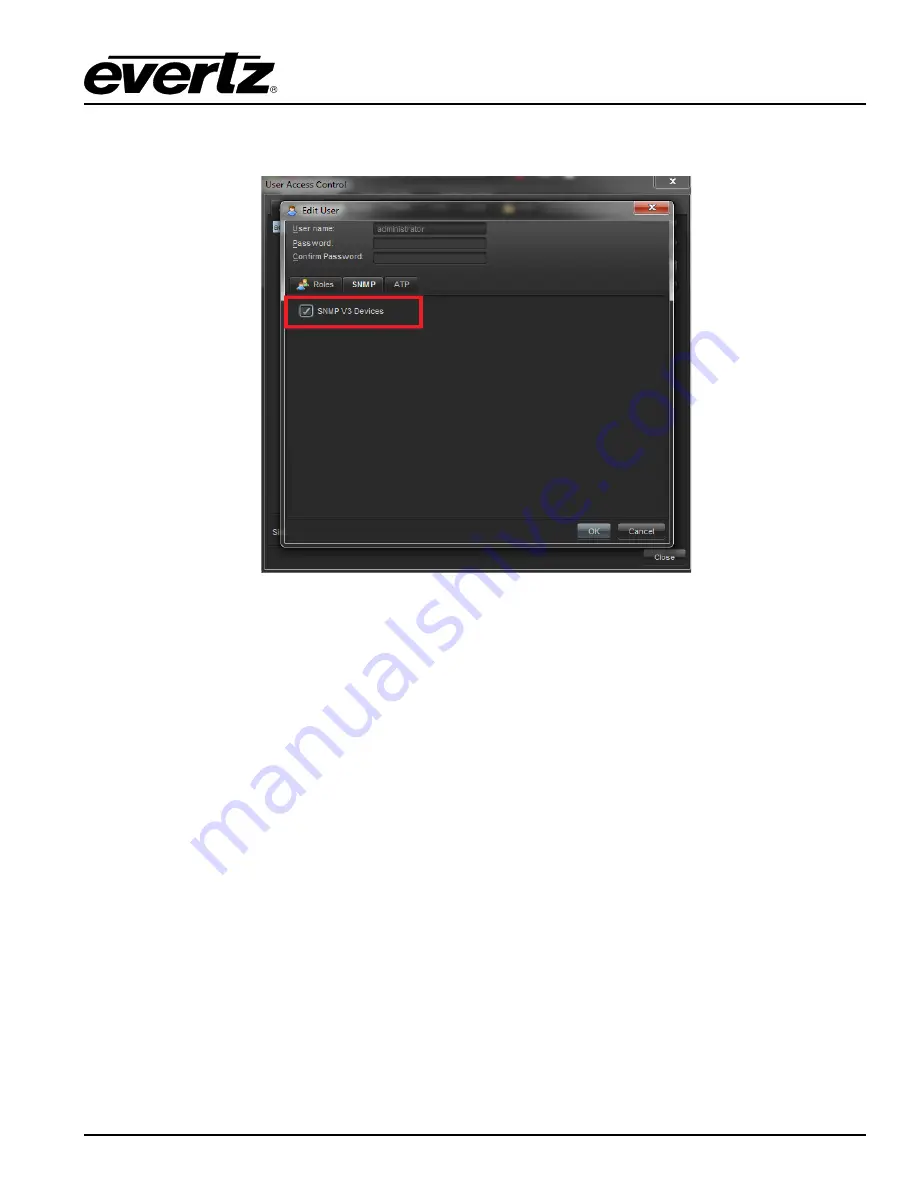
11. Navigate to the User’s SNMP V3 TAB and add a checkmark to the desired SNMP V3 Group(s) for 

authentication. 


Figure 7-7: SNMP V3 Group(s) Authentication 


12. Click OK to save. 
 
13. Reboot VistaLINK

®

 Pro Client and Server.  

 
14. The 2432TX-2 will now be configured with SNMP V3. 


Содержание 2432TX-2

Страница 1: ...tion that is the property of Evertz Microsystems and is intended solely for the use of purchasers of the 2432TX 2 Series products Evertz Microsystems expressly prohibits the use of this manual for any purpose other than the operation of the device Due to ongoing research and development features and specifications in this manual are subject to change without notice All rights reserved No part of t...

Страница 2: ...This page left intentionally blank ...

Страница 3: ...IGITAL DEVICE OR PERIPHERAL This equipment has been tested and found to comply with the limits for a Class A digital device pursuant to Part 15 of the FCC Rules These limits are designed to provide reasonable protection against harmful interference when the equipment is operated in a commercial environment This equipment generates uses and can radiate radio frequency energy and if not installed an...

Страница 4: ...This page left intentionally blank ...

Страница 5: ...e only warranty offered by Evertz in relation to this product is the Evertz standard limited warranty stated in the sales contract or order confirmation form Although every attempt has been made to accurately describe the features installation and operation of this product in this manual no warranty is granted nor liability assumed in relation to any errors or omissions unless specifically underta...

Страница 6: ...2432TX 2 Dual Path Dual Link DVI to Serial Converter Page ii Revision 1 0 This page left intentionally blank ...

Страница 7: ...1 USER CONTROLS 9 4 1 1 Dip Switches 9 4 2 ACCESSING THE SERIAL PORT MENU 10 4 3 SERIAL MENU 10 4 3 1 Network Configuration 11 4 3 2 Hardware Version Information 11 4 3 3 Video Utilities Menu 11 4 3 4 Video Standard Information 12 4 3 5 Set Analog Offsets 12 4 3 6 Lock Input Mode 13 4 3 7 Enable HDCP Content Processing 13 4 3 8 EDID Configuration 14 4 3 9 Output Configuration Menu 17 4 3 10 Scaler...

Страница 8: ...mpleting the Upgrade 29 6 2 FTP UPGRADE METHOD 30 7 2432TX 2 CONFIGURATION USING VISTALINK PRO 31 7 1 SNMP V1 31 7 2 CONFIGURING VLPRO FOR SNMP V3 33 7 3 2432TX 2 VISTALINK CONFIGURATION VIEW 36 7 3 1 General Tab 38 7 3 2 Monitor 38 7 3 3 Control 39 7 3 4 Input Monitor 39 7 3 5 Input Control 40 7 3 6 Output Monitor 42 7 3 7 Output Control 42 7 3 8 Video Control 43 7 3 9 Scaler Control 44 ...

Страница 9: ...Scan Mode 18 Figure 4 19 Set Frame Rate 18 Figure 4 20 Scaler Configuration Menu 18 Figure 4 21 SNMP Configuration 19 Figure 4 22SNMP V1 Setup Menu 19 Figure 4 23 SNMP V3 Setup Menu 20 Figure 4 24 SNMP V3 User Setup 20 Figure 4 25 Add Edit SNMP V3 User 21 Figure 4 26 Remove SNMP V3 User 21 Figure 4 27 Show All SNMP V3 User 22 Figure 4 28 SNMP V3 Access Control Setup 22 Figure 4 29 Add SNMP V3 Acce...

Страница 10: ...ut Monitor Menu 42 Figure 7 15 Output Control Menu 42 Figure 7 16 Video Control Menu 43 Figure 7 17 Scaler Control Menu 44 TABLES Table 2 1 DVI I Input Connector 3 Table 2 2 DB9 Port Pin Out 5 Table 4 1 DIP Switch Functions 9 Table 4 2 Serial Port Terminal Settings 10 Table 6 1 Serial Terminal Settings 28 Table 6 2 Serial Terminal Settings 30 ...

Страница 11: ...rts two independent DVI VGA or component inputs Provides serial digital outputs via coax as standard and via hot pluggable SFPs with the fiber optics option installed Supports SMPTE standard serial digital outputs for applications where DVI VGA or component video conversion to SDI is required Configurable input scaling to best fit SMPTE 259M 292M or 424M standard Full 24 bits per pixel color resol...

Страница 12: ...2432TX 2 Dual Path Dual Link DVI to Serial Converter Page 2 Revision 1 0 OVERVIEW This page left intentionally blank ...

Страница 13: ...y cord to the power entry module on the DC voltage adapter The power cord needs to be minimum 18 AWG wire size type SST marked VW 1 maximum 2 5m in length The DC cable of the voltage adapter needs to be connected to the DC power jack on the side panel A green LED located beside the DIP switch connector will be illuminated when power is applied to 2432TX 2 2 2 DVI I CONNECTORS DVI I connector is fo...

Страница 14: ...Connectors 2 3 BNC CONNECTORS BNC connectors are used for serial digital outputs 4 BNC connectors and analog audio input 4 BNC connectors Figure 2 3 2432TX 2 Rear View BNC Connectors 2 4 FIBER CONNECTORS OPTIONAL 2 SFP s SFP3T 13 2 are used for serial digital output over fiber Figure 2 4 2432TX 2 Rear View Fiber Connectors ...

Страница 15: ...e 9 pin D connector used for connecting to a standard computer serial below table shows the pin out of the female DB 9 connector Pin Name Description 1 2 TxD RS 232 Transmit Output 3 RxD RS 232 Receive Input 4 5 Sig Gnd RS 232 Signal Ground 6 7 8 9 Table 2 2 DB9 Port Pin Out Figure 2 5 2432TX 2 Front View DB9 Connector ...

Страница 16: ...ng assembly can only be connected in one way and with very good repeatability The fiber interconnect panel that is provided with each product can be ordered with optional SC PC ST PC or FC PC connectors The customer is required to provide the optical fiber with the correct connectors to connect the modules together SC PC ST PC and FC PC interconnection housing and connectors as well as adapters ar...

Страница 17: ...kHz THD 0 5 20Hz to 20KHz Channel Phase Difference 1 SNR 75 dB Maximum Input Level 2 dBu Signal Quantization 24 bits 48 kHz Genlock Number of Inputs 1 Connectors BNC per IEC 60169 8 Amendment 2 Termination 75 Ω internal SDI Output Number of Outputs 2 Total 4 BNCs are used if Dual link transmission mode is used Connectors BNC per IEC 60169 8 Amendment 2 Standard SMPTE 259M 292M 424M and Evertz prop...

Страница 18: ...ns With flanges 7 81 L x 5 63 W x 1 75 H 199mm L x 143mm W x 45mm H Compliance Electrical Safety Power supply UL listed Complies with CE Low Voltage Directive Laser Safety Class 1 laser product Complies with 24 CFR 1040 10 and 1040 11 IEC 60825 1 EMI RFI Complies with FCC Part 15 Class A EU EMC directive ...

Страница 19: ... Input 1B 4 When On this LED indicates that the 2432TX 2 is outputting a signal on Input 2B Figure 4 1 2432TX 2 Status LEDs 4 1 USER CONTROLS 4 1 1 Dip Switches Note DIP Switch settings are only valid with Version 1 X X firmware With firmware version 2 X X DIP switches are inactive due to functions being moved to serial menu and SNMP for control DIP Switch Function 1 Output format DOWN SDI UP 3G G...

Страница 20: ...s until the initial configuration has been completed Connect the 9 pin D type end of the serial cable to the serial port of your computer Open a terminal session and configure the port for the following configuration Table 4 2 Serial Port Terminal Settings 4 3 SERIAL MENU Configure your terminal program to the above table settings and press the enter button The session should respond with the 2432...

Страница 21: ...e Figure 4 4 Network Configuration 4 3 2 Hardware Version Information This menu is used to retrieve device information Figure 4 5 Hardware Version Information 4 3 3 Video Utilities Menu This menu has multiple sub menus for Video Standard Information setting Analog Offsets Input locking and HDCP content management Below menu highlight menu structure Figure 4 6 Video Utilities Menu ...

Страница 22: ...information regarding current input resolution information by selecting input number Figure 4 7 Video Standard Information 4 3 5 Set Analog Offsets This menu allows setting vertical and horizontal offsets for current input retrieve current offsets information and allow reset the offset through serial sub menu options Figure 4 8 Set Analog Offsets ...

Страница 23: ...nputs are detected and transmitted 3 Digital Priority Detects digital inputs first if not detected then will detect analog signal 4 Analog Priority Detects analog signal first if not detected then will detect digital signal Figure 4 9 Lock Input Mode 4 3 7 Enable HDCP Content Processing This menu allows user to enables disables HDCP content Processing and enforce encryption for HDCP encrypted cont...

Страница 24: ...ial Converter Page 14 Revision 1 0 STATUS LEDS 4 3 8 EDID Configuration This menu allow user to verify supported EDID resolutions Users can verify the EDID settings and also modify EDID settings for each input Figure 4 11 EDID Configuration ...

Страница 25: ...2432TX 2 Dual Path Dual Link DVI to Serial Converter STATUS LEDS Revision 1 0 Page 15 1 Show supported EDID resolutions Figure 4 12 Show Supported EDID Resolutions 2 Show EDID Contents ...

Страница 26: ...settings in one of four modes a DVI factory default EDID setting contains common VESA resolutions b Custom DVI enables user to create a custom native and secondary resolution c Analog factory default EDID setting contains common Analog resolutions d Custom Analog enables user to create a custom native and secondary analog resolution Figure 4 14 Modify EDID Contents ...

Страница 27: ...andwidth set scan mode and set frame rate Figure 4 15 Output Configuration Menu 1 Set Serial Digital Output Format allow user to switch between SDI and 3G Glink output Evertz proprietary format Figure 4 16 Set Serial Digital Output Format 2 Set Maximum Bandwidth Limit allows user to set per output bandwidth to be 2 97Gb s or 1 485Gb s Figure 4 17 Set Maximum Bandwidth Limit ...

Страница 28: ...to set each output to be progressive and interlace Figure 4 18 Set Scan Mode 4 Set Frame Rate allow user to set frame per out to be 59 94fps or 50fps Figure 4 19 Set Frame Rate 4 3 10 Scaler Configuration Menu This menu allows user to enable or disable output scaling per input Figure 4 20 Scaler Configuration Menu ...

Страница 29: ...nd V3 settings Figure 4 21 SNMP Configuration 1 SNMP V1 Setup allows user to configuration Trap destination and Community strings read and write for SNMP V1 Figure 4 22SNMP V1 Setup Menu 2 SNMP V3 Setup allows user to configure SNMP V3 settings 3 SNMP Version allows user to set SNMP V3 version used for control and trap sending Version 1 and 3 are supported ...

Страница 30: ...US LEDS 4 3 12 SNMP V3 Setup Menu This menu allow user to setup profile and encryption access control and trap address control Figure 4 23 SNMP V3 Setup Menu 1 SNMP V3 User Setup allows user to add up to 10 SNMP V3 user profiles and encryption types Figure 4 24 SNMP V3 User Setup ...

Страница 31: ...n Password allow user to set password used for user authentication 4 User Privacy allow user to set DES or AES packet encryption 5 Encryption Password allow user to set password used for packet encryption 6 Select Access Control model allow user to set access control model used by default it is configured to allow read write and notifications to be sent to the user 7 Select User to Edit allow user...

Страница 32: ...1 0 STATUS LEDS C Show All SNMP V3 User allows user to verify which user has authentication to access the unit Figure 4 27 Show All SNMP V3 User 2 SNMP V3 Access Control Setup allows user to limit read write access for specific OID Figure 4 28 SNMP V3 Access Control Setup ...

Страница 33: ...0 Page 23 A Add EDIT SNMP V3 Access Control allow user to specify read write control on a per user basis for any OID Figure 4 29 Add SNMP V3 Access Control B Remove SNMP V3 Access Control allows user to remove access controls for a user Figure 4 30 Remove SNMP V3 Access Control ...

Страница 34: ...ess control settings on the 2432TX 2 Figure 4 31 Show All SNMP V3 Access Control 3 SNMP V3 Notifications Setup allow user to set trap destination and remove trap destination for SNMP V3 Figure 4 32 SNMP V3 Notification Setup A Add SNMP V3 Notification Destination allow user to set trap destination IP address Figure 4 33 Add SNMP V3 Notification Destination ...

Страница 35: ... notification settings on the unit Figure 4 34 Remove SNMP Notification 4 3 13 SNMP Version This menu allows user to set unit to communicate using SNMP V1 or V3 version Figure 4 35 SNMP Version A SNMP Get Set Version Setup allow user to set SNMP V1 or V3 version used for configuration and update Figure 4 36 SNMO Get Set Version Setup ...

Страница 36: ...32TX 2 Dual Path Dual Link DVI to Serial Converter Page 26 Revision 1 0 STATUS LEDS B SNMP Trap Version Setup allow user to set SNMP V1 or V3 version used to send traps Figure 4 37 SNMP Trap Version Setup ...

Страница 37: ... ENGINEERING MENU Revision 1 0 Page 27 5 ENGINEERING MENU This menu is for Evertz personnel only You may be requested to access and execute options within this menu when seeking technical support from Evertz Guidance will be given should this be required ...

Страница 38: ...for about 5 seconds then the unit will continue to boot For example EVERTZ MCF5272 MONITOR 2 3 BUILD 3 66 MHZ COPYRIGHT 1997 1998 1999 2000 2001 2002 EVERTZ MICROSYSTEMS LTD 28F160C3B FLASH DETECTED PROD 2430TX 2 MCF5272 COLD BOOT 1 The following is a list of possible reasons for failed communications Defective serial cable Wrong communications port selected in the terminal program Improper port s...

Страница 39: ...of the upload 3 For example UPLOAD OKAY 7700PB COLD BOOT 4 The following is a list of possible reasons for a failed upload If you get the message transfer cancelled by remote you must restart the terminal program and load the bin file then cycle power to the unit The supplied bin file is corrupt Wrong file specified to be uploaded The PC s RS 232 communications port cannot handle a port speed of 1...

Страница 40: ... enter the IP address Once complete press the enter key 7 Select Option 2 Set Netmask and enter the netmask Once complete press the enter key 8 Press S to save and exit 9 Reboot the unit 10 Open a command prompt on the computer where 2432TX 2 network cable is plugged 11 Ping the 2432TX 2 to confirm it is reachable from the computer 12 Ftp to the unit Press enter for user name and password 13 Type ...

Страница 41: ...rver Default login is administrator with no password 4 Go to Help apply update product and browse to the jar file location of 2432TX 2 Figure 7 1 Configuring VistaLINK PRO 5 VistaLINK Pro will ask you to reboot select OK 6 When VistaLINK Pro Server reboots login and launch VistaLINK Pro client 7 Inside VistaLINK Pro client select the tree menu bar add update agent enter IP address of the 2432TX 2 ...

Страница 42: ...2432TX 2 Dual Path Dual Link DVI to Serial Converter Page 32 Revision 1 0 VISTALINK PRO Figure 7 2 Configuration Page for 2432TX 2 ...

Страница 43: ...MP V3 1 Launch VistaLINK PRO Server and Client 2 Go to tools User a menu will appear Figure 7 3 Server SNMP Communications User 3 Make sure Server SNMP Communications user is set to current User See Figure 7 3 4 Click the add button and another context menu will appear Figure 7 4 Add an SNMP Name for the SNMP V3 Role ...

Страница 44: ...ation and encryption 6 Click the Add button to add a new device 7 Enter IP of the unit and select password encryption type MD5 or SHA 1 8 Enter the username specified on the 2432TX 2 unit for authentication 9 Add the authentication password if any and the encryption password if any in the dialog box Click OK Figure 7 5 Add Authentication Password 10 Navigate to user tab Select username and click E...

Страница 45: ... 1 0 Page 35 11 Navigate to the User s SNMP V3 TAB and add a checkmark to the desired SNMP V3 Group s for authentication Figure 7 7 SNMP V3 Group s Authentication 12 Click OK to save 13 Reboot VistaLINK Pro Client and Server 14 The 2432TX 2 will now be configured with SNMP V3 ...

Страница 46: ...n 1 0 VISTALINK PRO 7 3 2432TX 2 VISTALINK CONFIGURATION VIEW 1 Configure 2432TX 2 with VistaLINK Pro right click on the IP address of 2432TX 2 Select View Configuration form the popup menu that appears as shown in below Figure 7 8 Configure 2432TX 2 with VistaLINK Pro ...

Страница 47: ... View Configuration is selected the user will be presented with the main configuration screen as shown below Figure 7 9 Main configuration Screen 3 The user can navigate through the tabs to adjust the configuration parameters Please see sections below for more information on configuring 2432TX 2 ...

Страница 48: ...r 50Hz Figure 7 10 General Tab Menu 7 3 2 Monitor Output Video Genlock Enable This field displays the current Genlock status of the 2432TX 2 unit Output Video Genlock Status This field displays the current Genlock format of the 2432TX 2 unit FPGA Temperature This field displays the current FPGA temperature in Celsius FPGA Core Voltage This field displays the current FPGA voltage Fan Status This fi...

Страница 49: ...to set the Video output frame rate of the unit to be 59 94Hz or 50Hz Figure 7 11 Control Note Settings are applied to both outputs 7 3 4 Input Monitor The General tab allows user to monitor both the inputs for input presence resolution standard signal type and signal is dual link or single link Figure 7 12 Input Monitor Menu ...

Страница 50: ...n This field display current resolution standard being detected on an input Signal Type This field display current signal type detected on an input Digital Analog or Component 7 3 5 Input Control The Input control tab allows user to set Input detection priority Enable HDCP signal processing set color mode color correction Horizontal offset and Vertical offset Figure 7 13 Input Control Menu Note In...

Страница 51: ...Pr RGB mode allows DVI VGA input and YPbPr mode allow component input Analog Gain Red This option allows user to apply red color gain for analog input between 0 255 range Analog Gain Blue This option allows user to apply blue color gain for analog input between 0 255 range Analog Gain Green This option allows user to apply green color gain for analog input between 0 255 range Analog Offset Red Thi...

Страница 52: ... allows user to monitor video output standard for the unit Figure 7 14 Output Monitor Menu Note Output monitor is available for Output 1 and Output 2 7 3 7 Output Control The Output Control allows user to set Video format Bandwidth Fields dual link signal output no signal colour scaling and cropping Figure 7 15 Output Control Menu ...

Страница 53: ... or 3Gb s Interlace This option allows user to set output to be Interlace or Progressive Dual Link CFG This option allows user to set the output raster option for dual link input where 2 SDI output are used 1 Odd Even Pixels Configure the output to send odd pixel on BNC A Fiber A and even pixel on BNC B Fiber B 2 Left Right Image Halves Configure the output to send Left half image on BNC A Fiber A...

Страница 54: ...k mode Mode This option allows user to set output to fill or maintain aspect ratio Resolution This option allows user to pick output resolution from drop down menu Crop Left This option allows user to set left starting pixel for crop Crop Top This option allows user to set top starting pixel for crop Crop Width This option allows user to set pixel width starting from left crop position Crop Height...

Отзывы: