


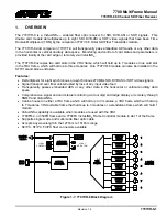
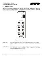


7700 MultiFrame Manual
7707VR-8 8 Channel SDI Fiber Receiver
7707VR-8-8
Revision
1.4
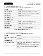
For brevity in the manual, only VCH1 will be discussed.
PSWD
VCH1-VCH8
DIS
EN
VCH1
Disable/Enable. When Disabled the data received on the fiber
link intended for output 1 is not output. This menu item is not
modifiable without entering the correct passcode, though its
current state is viewable.
The functionality is similar for menu selections VCH2 through VCH8.
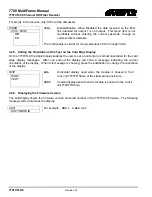
4.2.5. Setting the Orientation of the Text on the Card Edge Display
On the 7707VR-8 the
DISP
display enables the user to set a horizontal or vertical orientation for the card
edge display messages. After one second the display will show a message indicating the current
orientation of the display. When this message is showing, press the pushbutton to change the orientation
of the display.
DISP
HORZ
VERT
HOR
Horizontal display used when the module is housed in the 1
rack unit 7701FR frame or the stand-alone enclosure.
VERT
Vertical display used when the module is housed in the 3-rack
unit 7700FR frame.
4.2.6. Displaying the Firmware Version
The
S/W
display shows the firmware version and build number of the 7707VR-8 firmware. The following
message will scroll across the display:
VER
SOFTWARE ID
For example:
VER 1.0 BLD 067