eIVP-CFS-AI-D0000
Intel® 8th Gen Core™ i5 AI Box
User’s Manual
Copyright © EverFocus Electronics Corp.
Release Date: February 2021
Страница 1: ...eIVP CFS AI D0000 Intel 8th Gen Core i5 AI Box User s Manual Copyright EverFocus Electronics Corp Release Date February 2021...
Страница 2: ...nd software version Information contained in this document is subject to change without notice Copyright All rights reserved No part of the contents of this manual may be reproduced or transmitted in...
Страница 3: ...spray detergents Make sure the device is installed near a power outlet and is easily accessible Keep this device away from humidity Place the device on a solid surface during installation to prevent...
Страница 4: ...e or equivalent type recommended by the manufacturer Dispose of used batteries according to the manufacturer s instructions and your local government s recycling or disposal directives Attention Il y...
Страница 5: ...ation 4 2 1 Removing the Housing Cover 4 2 2 Memory Modules SO DIMM Installation 5 2 3 M 2 SSD Module Installation 6 2 4 M 2 WiFi BT Module Installation 7 2 5 2 5 SATA HDD Installation 8 2 6 VESA Moun...
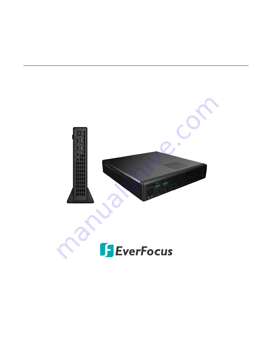
Страница 6: ...tivity wise the eIVP CFS AI D0000 supports additional M 2 key E 2230 slot for wireless connection one RS 232 COM port and two USB 3 1 Gen 1 Type A ports two USB 3 1 Gen 1 type C ports and four USB2 0...
Страница 7: ...side WiFi antenna x 2 only for models built in with WiFi module Stand bracket x 1 VESA mount bracket and screw package x 1 Note 1 Equipment configurations and supplied accessories vary by country Plea...
Страница 8: ...Port USB31_TC_2 1 5 Rear Panel 1 2 3 4 5 6 7 8 9 10 10 No Description No Description 1 Headphone Jack Audio Line Out 6 LAN RJ 45 Port Refer to Note 2 Display Port 7 USB2 0 Ports USB_4_5 3 HDMI Port 8...
Страница 9: ...4 2 Connection and Installation 2 1 Removing the Housing Cover Make sure the system is power off Unscrew the two screws on the rear panel slightly pull the cover backward and then lift up the cover to...
Страница 10: ...DDR2 or DDR3 which may cause damage to the motherboard and SO DIMM 2 The SO DIMM only fits in one correct orientation It will cause permanent damage to the motherboard and SO DIMM if you force the SO...
Страница 11: ...2 PCIe module up to Gen3 x4 32Gb s 1 Prepare a M 2 SSD module and a screw 2 Gently insert the M 2 SSD module into the M 2 slot Please be aware that the M 2 SSD module only fits in one orientation 3 T...
Страница 12: ...y insert the wireless module into the M 2 slot Please be aware that the M 2 SSD module only fits in one orientation 3 Tighten the screw to secure the module into place Please do not overtighten the sc...
Страница 13: ...stem 1 Make sure the system is power off and remove the housing cover 2 Use the provided screws to secure the HDD on the HDD holder 3 Pull the release lever of the HDD bracket outward Place the HDD in...
Страница 14: ...vided VESA mount bracket and screw package to install the system on the rear side of a monitor 1 Screw the VESA mount plate to the rear side of a monitor 2 Slide the system into the VESA mount plate a...
Страница 15: ...ut 1 2 3 4 5 6 7 8 No Description 1 Clear CMOS Jumper CLRMOS1 2 2 x 260 pin DDR4 SO DIMM Slots DDR4_A1 DDR4_B1 3 CPU Fan Connector CPU_FAN1 4 2 5W Mono Out Speaker Header MONO1 5 SATA3 Connector SATA0...
Страница 16: ...then shut it down before you do the clear CMOS action Please be noted that the password date time and user default profile will be cleared only if the CMOS battery is removed Note 1 The Clear CMOS Bu...
Страница 17: ...t flash in case there is problem with the data Refer to No 6 in 3 1 Motherboard Layout 2 5W Audio Amp Output Header MONO1 Please connect the chassis speaker to this header Refer to No 4 in 3 1 Motherb...
Страница 18: ...product is designed and manufactured with high quality materials and components which can be recycled and reused This symbol means that electrical and electronic equipment at their end of life should...