


9
EUROPORT EPA900 User Manual
5. Specifications
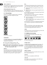
Inputs 1-4
Type
4 x XLR, electronically balanced,
4 x ¼" TRS jack, electronically balanced
Impedance
approx. 2.2 kΩ , balanced,
approx. 1.1 kΩ , unbalanced
Input sensitivity
-21 dBu @ PAD/OFF
Max. gain
+30 dB to +10 dB
Phantom power supply
+48 V
Signal-to-noise ratio
-90 dB, A-weighted
Channel separation
70 dB
Inputs 5-8
Type
4 x ¼" TS jack, unbalanced
4 x RCA phono jack, unbalanced
Impedance
approx. 20 kΩ , unbalanced
Input sensitivity
-15 dBu
Max. gain
+20 dB
Signal-to-noise ratio
-85 dB, A-weighted
Stereo Aux In
Type
1 x ¼" TS jack, unbalanced
1 x stereo minijack, unbalanced
Impedance
approx. 100 kΩ , unbalanced
Input sensitivity
-8 dBu
Signal-to-noise ratio
-90 dB, A-weighted
Tape Out
Type
2 x cinch jack, unbalanced
Impedance
approx. 1 kΩ
Max. output level
+17 dBu, unbalanced
Channel separation
> 70 dB
Sub Out
Type
1 x ¼" stereo jack, unbalanced
Impedance
approx. 1 kΩ
Max. output level
+ 21 dBu, unbalanced
Channel EQ
BASS
±15 dB @ 80 Hz
TREBLE
±15 dB @ 27 kHz
Effects
Converter
24-bit delta-sigma
Sampling frequency
40 kHz
Display
2-digit, 7-segment
EQ
Type 7-band
Loudspeaker Outputs
Type
2 x ¼" TS jack
Load impedance
8 Ω
Output Power
RMS @ 1% THD (sine signal)
8 Ω 2 x 360 W; 4 Ω 2 x 400 W
Peak power
8 Ω 2 x 400 W; 4 Ω 2 x 450 W
System Specifications
Frequency response
50 Hz to 44 kHz, ± 3 dB
Distortion (THD + N)
0.32% @ 1 W
Power Supply
Power consumption
1,000 W
Fuse
T 10 A H 250 V (100 –120 V~, 50/60 Hz)
T 10 A H 250 V (220 –240 V~, 50/60 Hz)
Dimensions/Weight
Dimensions (H x W x D)
approx. 26.0 x 13.9 x 34.8"
approx. 660 x 354 x 883 mm
Weight
approx. 82.5 lbs / 37.5 kg
BEHRINGER is constantly striving to manintain the highest professional standards. As a result of these efforts,
modifications may be made from time to time to existing products without prior notice. Specifications and
appearance may differ from those listed or liiustrated.
Содержание EPA900
Страница 12: ...We Hear You ...