Europort EPA900 Скачать руководство пользователя страница 8

8

EUROPORT EPA900 User Manual

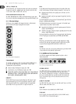
3.9  Power supply and serial number

FUSE HOLDER/IEC SOCKET

Connection to an AC power supply is made via an IEC socket. It complies with 

applicable safety regulations. A suitable AC power cord is included. Replace the 

fuse with a fuse of the same type.

Fig. 3.9: Power supply and fuse

◊ 

To avoid an electric shock, turn off and unplug the unit before replacing 
the fuse.

POWER Switch

Use the POWER switch to start up the unit. The POWER switch should be in the 

“Off” position when you connect the unit to the AC power supply.
To disconnect the unit from the power supply, pull out the power plug. 

When starting up the unit, ensure that the power plug is easily accessible.

◊ 

Please note: Switching the POWER switch off does not completely 
disconnect the unit from the power supply. For this reason, you should 
unplug the power cord if the unit is not going to be used for a long 
period of time.

VOLTAGE SELECTOR

The VOLTAGE SELECTOR switch lets you set the correct operating voltage.

◊ 

Before connecting the unit to the mains, please check that it is set to 
the correct supply voltage.

◊ 

You have to use another fuse if you set the unit to another supply 
voltage. The correct value is specified in Chapter “Specifications”.

SERIAL NUMBER

The serial number can be found on the back of the mixer. It is needed for 

online registration.

4.  Applications

The EPA900 can be used for simple sound tasks, e.g., amplification of the 

presenter’s voice, playback sound, or karaoke applications, as well as for 

demanding tasks such as band amplification or stage monitor sound. A typical 

example of use as a sound system for music with live instruments and players is 

given below.

EPA900

Keyboard

CD player

Drum Computer

ULTRAVOICE XM8500

Electric Guitar

GMX212

Stereo

AUX In

In 3

In 1

In 2

In 5/6

In 7/8

Speaker Output

Lef/Main

Fig. 4.1: Sound example

Содержание EPA900

Страница 1: ...User Manual EUROPORT EPA900 Ultra Compact 900 Watt 8 Channel Portable PA System with Digital Effects and FBQ Feedback Detection ...

Страница 2: ...pplied loudspeakers a microphone including cable you can get going right away With the EPA900 you can quickly and easily master any sound situation We at BEHRINGER hope you enjoy your new acquisition Table of Contents Thank you 2 Important Safety Instructions 3 Legal Disclaimer 3 Limited warranty 3 1 Before You Get Started 4 1 1 Shipment 4 1 2 Initial operation 4 1 3 Online registration 4 2 Instal...

Страница 3: ...ularlyatplugs conveniencereceptacles andthepointwheretheyexitfromtheapparatus 11 Useonlyattachments accessoriesspecifiedby themanufacturer 12 Useonlywiththe cart stand tripod bracket ortablespecifiedbythe manufacturer orsoldwith theapparatus Whenacart isused usecautionwhen movingthecart apparatus combinationtoavoid injuryfromtip over 13 Unplugthisapparatusduringlightningstormsor whenunusedforlongp...

Страница 4: ...ient electrical contact to earth otherwise electrostatic discharges might affect the operation of the unit The sound quality may diminish within the range of powerful broadcasting stations and high frequency sources Increase the distance between the transmitter and the device and use shielded cables for all connections 1 3 Online registration Please register your new BEHRINGER equipment right afte...

Страница 5: ...use its channels separately mono such as when used for FOH PA and stage Depending on the requirements one stereo or two independent mono sounds can be run An internal effect can be used as an AUX effect from each channel The 7 band graphic equalizer is used to process the stereo bus or the two mono paths 3 1 Mono Channels 1 4 Channels 1 4 are designed as mono channels and are used to connect micro...

Страница 6: ...e signal only on the right side that is the RIGHT MAIN path Positions between these settings will result in a proportionate signal allocation between LEFT MAIN and RIGHT MAIN The BAL control determines the levels of a stereo source s left and right input signals in relation to each other Turn the control completely to the left to hear only the left signal component of the stereo source on the LEFT...

Страница 7: ...It is permanently integrated into the mixer as a Send Return effect i e an adjustable signal portion can be routed to the effects unit from every input channel The selected effect is applied to the signal portions of the channels and the signals are then mixed with the direct signals via the stereo bus Fig 3 7 Internal 24 bit multieffects unit CLIP SIG The CLIP and SIG LEDs provide information on ...

Страница 8: ...hould unplug the power cord if the unit is not going to be used for a long period of time VOLTAGE SELECTOR The VOLTAGE SELECTOR switch lets you set the correct operating voltage Before connecting the unit to the mains please check that it is set to the correct supply voltage You have to use another fuse if you set the unit to another supply voltage The correct value is specified in Chapter Specifi...

Страница 9: ...Channel separation 70 dB Sub Out Type 1 x stereo jack unbalanced Impedance approx 1 kΩ Max output level 21 dBu unbalanced Channel EQ BASS 15 dB 80 Hz TREBLE 15 dB 27 kHz Effects Converter 24 bit delta sigma Sampling frequency 40 kHz Display 2 digit 7 segment EQ Type 7 band Loudspeaker Outputs Type 2 x TS jack Load impedance 8 Ω Output Power RMS 1 THD sine signal 8 Ω 2 x 360 W 4 Ω 2 x 400 W Peak po...

Страница 10: ...E approx 1 2s reverb decay 73 HEAVY PHASER Extreme strong effect 24 DRUMS PLATE approx 1 0s reverb decay 74 PITCH SHIFT DETUNE 2 3 times detune for a wider solo voice sound 25 GOLD PLATE 1 approx 1 2s reverb decay 75 PITCH SHIFT 3 Minor third added voice 26 GOLD PLATE 2 approx 2 0s reverb decay 76 PITCH SHIFT 4 Major third added voice 27 SHORT SPRING approx 1 0s reverb decay 77 PITCH SHIFT 7 Quint...

Страница 11: ... that interference will not occur in a particular installation If this equipment does cause harmful interference to radio or television reception which can be determined by turning the equipment off and on the user is encouraged to try to correct the interference by one or more of the following measures Reorient or relocate the receiving antenna Increase the separation between the equipment and re...

Страница 12: ...We Hear You ...

Отзывы: