SD20-G Series
97
6.1 Basic parameters setting
6.1.1 Before running
Make sure that all wiring has been completed.
Wiring
1
Connect L1
(
R
)
、
L2
(
S
)
、
L3
(
T
)
of servo drive to main circuit power.
2
Connect U/V/W of servo drive to U/V/W of servo motor well.
3
Check all control signal cables are connected correctly, and check the brake,
overtravel and the other protrective functions for correct operation.
4
Servo drive and servo motor must be grounded reliably.
5
When external resistor is used, please remove short wires between B2 and B3.
Environment and machinery
1
There is no iron dust or foreign matter in the servo drive.
2
There is no inflammable substance nearby servo drive and external braking
resistor.
3
Servo motor is reliably connected to mechanical equipment.
6.1.2 Power on
1) Power on control circuit and main circuit.
Pease connect power to L1
(
R
)
、
L2
(
S
)
、
L3
(
T
)
.
●
Power on control circuit and main circuit, if bus voltage indicator shows no abnormal, and “0” is displayed
in the keypad, it indicates servo drive is enabled.
●
If “AL-xx” is displayed in the keypad, please refer to Chapter 9.
2)Set S-ON to OFF status.
SD20 servo drive supports internal two modes to set S-ON , including internal parameter and DI terminal.
User can set S-ON by internal parameter Po004 and Po100.
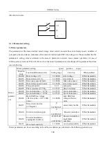
User can also set DI terminal of servo drive to FunIN. 1: S-ON, and make sure the DI terminal is valid. Then set
DI terminal to invalid status by PC/PLC or external switch.
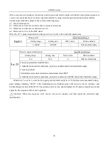
Po004
Servo-on mode Speed Position Torque
Setting range
Setting unit
Mfr’s value
Effect
0
~
6
N/A
0
Repower on
0: External terminal enabled, there must be input terminal, which is set SON-I function.
1: Internal parameter enabled, which is determined by Po100.
2: Two-line mode 1 3. Two-line mode 2 4. Three-line mode 1
Содержание SD20-G Series
Страница 35: ...SD20 G Series 35 M3 structure Fig 3 1 5 Servo drive structure 3...
Страница 36: ...SD20 G Series 36 ML3 structure 118 5 5 7 5 93 297 8 223 118 93 0 5 12 5 7 5 4 M4...
Страница 38: ...SD20 G Series 38 M4 structure Approx mass 10 365 kg Fig 3 1 7 Servo drive structure 5...
Страница 39: ...SD20 G Series 39 M5 structure Approx msaa 11 1Kg Fig 3 1 8 Servo drive structure 6...
Страница 40: ...SD20 G Series 40 M6 structure Approx mass 17 4Kg Fig 3 1 9 Servo drive structure 7...
Страница 182: ...SD20 G Series 182 Fig 6 4 44SD20E Cam internal frameworkdiagram...


