SD20-G Series
75
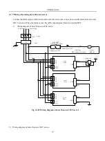
4.3.7 Wiring when using more than one servos
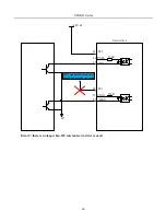
Connect the alarm output (ALM) terminals for the three Servodrives in series to enable alarm detection relay
RLY to operate. When the alarm occurs, the ALM output signal transistor is turned OFF.
1)
Wiring diagram of more than one 220V servos
Alarm relay
RLY
Common-open contact
Contactor
KM1
Common-open contact
KM1
L 1
L 2
L 3
L 1 C
L 2 C
QF
breaker
AC three-phase
220V
power supply
ALM+
ALM -
+24V
RLY
Servo
drive
CN3
Contact
KM1
coil
Manual power ON
Filter
L 1
L 2
L 3
L 1 C
L 2 C
ALM+
ALM-
CN3
L 1
L 2
L 3
L 1 C
L 2 C
ALM+
ALM-
CN3
0V
FIL
Servo
drive
Servo
drive
Manual power OFF
Alarm relay
Fig 4.3.22 Wiring diagram of more than one 220V servos
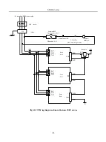
2) Wiring diagram of more than one 380V servos
Содержание SD20-G Series
Страница 35: ...SD20 G Series 35 M3 structure Fig 3 1 5 Servo drive structure 3...
Страница 36: ...SD20 G Series 36 ML3 structure 118 5 5 7 5 93 297 8 223 118 93 0 5 12 5 7 5 4 M4...
Страница 38: ...SD20 G Series 38 M4 structure Approx mass 10 365 kg Fig 3 1 7 Servo drive structure 5...
Страница 39: ...SD20 G Series 39 M5 structure Approx msaa 11 1Kg Fig 3 1 8 Servo drive structure 6...
Страница 40: ...SD20 G Series 40 M6 structure Approx mass 17 4Kg Fig 3 1 9 Servo drive structure 7...
Страница 182: ...SD20 G Series 182 Fig 6 4 44SD20E Cam internal frameworkdiagram...

