SD20-G Series
68
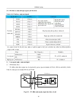
happen:
1.
Some input pulse could be missed.
;
2.
There will be large interference when servo drive receives pulse.
4.3.2 Analog command input signal and functions
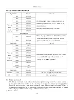
Signal name
Pin No.
Function
Analog
AS1+
CN3-23
Resolution of analog input signal is 12 bits, input
voltage range is -10V-+10V.
AS2+
CN3-25
GND
CN3-24
Analog input signal reference terminal.
Speed and torque signal input terminals are AS1+ and AS2+, resolution is 12 bits. The voltage value is set
byPo400/Po401.
Input voltage range: -10V-+10V, resolution is 12 bits.
Max voltage is ±12V.
Input resistor is about 50KΩ.
25
AS2+
AS1+
23
24
GND
GND
24
Lowpass filter
A/ D covert
- 10V- +10V
- 10V-+10V
Lowpass filter
Fig 4.3.11 Analog input interface circuit
4.3.3 Analog output signal and functions
SERVO DRIVE
D/A
1
24
AO1
AGND
V
SERVO DRIVE
D/A
14
24
AO2
AGND
V
Fig 4.3.12 Analog monitor output interface
The voltage range of analog monitor is 0~10V, the range of output current is 0~10mA.
Signal
Monitor content
AO1, AO2
Motor speed, bus voltage, and servo drive output current.
Содержание SD20-G Series
Страница 35: ...SD20 G Series 35 M3 structure Fig 3 1 5 Servo drive structure 3...
Страница 36: ...SD20 G Series 36 ML3 structure 118 5 5 7 5 93 297 8 223 118 93 0 5 12 5 7 5 4 M4...
Страница 38: ...SD20 G Series 38 M4 structure Approx mass 10 365 kg Fig 3 1 7 Servo drive structure 5...
Страница 39: ...SD20 G Series 39 M5 structure Approx msaa 11 1Kg Fig 3 1 8 Servo drive structure 6...
Страница 40: ...SD20 G Series 40 M6 structure Approx mass 17 4Kg Fig 3 1 9 Servo drive structure 7...
Страница 182: ...SD20 G Series 182 Fig 6 4 44SD20E Cam internal frameworkdiagram...

