SD20-G Series
263
control is 4~6 times higher than that in position mode control, when position response frequency is
higher than speed response frequency, the machinery could shake or position overshoot. When inertia
ratio becomes larger, the speed response of control system goes down and becomes unstable. Generally
increase the speed loop gain, but when the speed loop gain is overlarge, vibration occurs in running or
stop status (abnormal sound), therefore, set the speed loop gain to 50%~80% of gain when vibration.
Increase speed response and integral time to reduce the overshoot of acel/decel; reduce integral time can
improve the rotation. Reducing speed control integral time can increase speed response and narrow speed
control error, but vibration and noise may happen.
Reduce the noises in speed mode and position mode; Increase filter time constant can reduce noise but
could slow down the response.
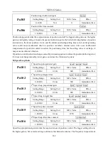
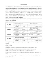
C) Torque Loop Gain
Po200
1
st
current loop bandwidth
speed position torque
Setting Range
Setting Unit
Mfr’s Value
Effect
10~3000
HZ
—
Immediate effect
Po201
2
nd
current loop bandwidth
speed position torque
Setting Range
Setting Unit
Mfr’s Value
Effect
10~3000
HZ
—
Immediate effect
Po214
1
st
torque filter time constant
speed position torque
Setting Range
Setting Unit
Mfr’s Value
Effect
0~30000
0.01ms
—
Immediate effect
Po215
2
nd
torque filter time constant
speed position torque
Setting Range
Setting Unit
Mfr’s Value
Effect
0~30000
0.01ms
—
Immediate effect
The larger current loop bandwidth is, the faster system response speed is, but the noise may be louder;
vice versa.
7.3.4 Gain Switch
Internal status or external DI can trigger gain-switching function, which has effects below:
● Switch to lower gain for vibration inhibition in the idle state of motor (servo enabled);
● Switch to higher gain for narrowing positioning time in the idle state of motor;
● Switch to higher gain for obtaining better instruction tracking performance in the running status of
motor;
● Switch different gain setting by external signal according to the condition of loading equipment;
(1)
User Parameter
Содержание SD20-G Series
Страница 35: ...SD20 G Series 35 M3 structure Fig 3 1 5 Servo drive structure 3...
Страница 36: ...SD20 G Series 36 ML3 structure 118 5 5 7 5 93 297 8 223 118 93 0 5 12 5 7 5 4 M4...
Страница 38: ...SD20 G Series 38 M4 structure Approx mass 10 365 kg Fig 3 1 7 Servo drive structure 5...
Страница 39: ...SD20 G Series 39 M5 structure Approx msaa 11 1Kg Fig 3 1 8 Servo drive structure 6...
Страница 40: ...SD20 G Series 40 M6 structure Approx mass 17 4Kg Fig 3 1 9 Servo drive structure 7...
Страница 182: ...SD20 G Series 182 Fig 6 4 44SD20E Cam internal frameworkdiagram...

