


ETK-V1.1 - User’s Guide
25
ETAS
Hardware Description
4.10
Nexus Interface
The ETK-V1.1 features a JTAG/Nexus debugging interface connector (Mictor 38
pin) as specified in the "The Nexus 5001 Forum - Standard for a Global Embed-
ded Processor Debug Interface, Version 2.0".
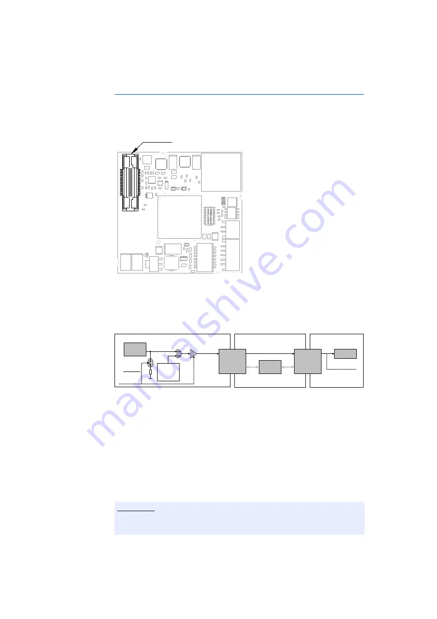
Fig. 4-13
Location of the Nexus Interface
This connector can be used to attach debug and trace tools (e.g. Lauterbach
debugger for MPC55xx - LA7610). All JTAG and Mictor interface signals are
directly connected to the corresponding signals on the VertiCal socket.
Fig. 4-14
Nexus TOOL_IO2 Signal Flow
The tool vendor specific signal TOOL_IO2 (TDET/WDT) can be used to control and
disable an external watchdog circuit on the ECU.
When the configuration parameter "Use TOOL_IO0 as Watchdog Disable?" is
set to "Yes" in the ETK Config Tool, the signal is driven from the Nexus connec-
tor to the signal TOOL_IO0 (Pin L22) of the VertiCal connector.
This signal is routed directly to a ball of the VertiCal base board, completely
bypassing the microcontroller on the VertiCal base board. Additionally, a 10
KOhm pulldown resistor is enabled at the Nexus connector to ensure a valid sig-
nal level, even if no debugger is connected to the JTAG/Nexus connector of the
ETKV1.0.
Note
A base board with optional balls (see chapter 9.2) must be assembled when
this feature is required.
Nexus Connector
ETKV1
ECU
VertiCal Base Board (416 / 324 / 208)
Pin 27
TOOL_IO2
Pin L22
TOOL_IO0
VertiCal
Connector
VertiCal
Base Board
Balls
M CU
Ball T19 (VertiCal 416)
Ball L16 (VertiCal 324)
Ball H19 (VertiCal 208)
TOOL_IO0
Watchdog
Conf igTool:
Use TOOL_IO0
as Wat chdog
Disable?
ProF
Command
(BDF)
OR
GND
10K
Nexus
Connector
1= disable
0= enable


