


ETAS
Functional Description
ES593.1-D
-
User Guide
20
5
Functional Description
This chapter describes the block diagram, power supply, Ethernet switch, mod
-
ule network, time synchronization, ECU interfaces and the firmware update.
5.1
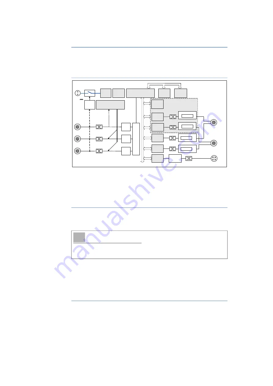
Block Diagram
Fig.
5
-
1
Block Diagram
To fulfill the operation demands in the vehicle, the interfaces of the ES593.1-D
are each routed to an Lemo socket.
5.2
Power Supply (7-29V DC)
The power supply interface (7-29V DC) is routed to a 2-pin connector (Lemo
socket) on the back panel of the module. Power is supplied to the module via
an external power supply or vehicle battery.
When the ES593.1-D is connected to the operating voltage and there is an
Ethernet connection at HOST, the module boots. If there is no Ethernet connec
-
tion, the module changes to “Standby.”
5.3
Ethernet Switch
The integrated Ethernet switch is used for the connection of the ES593.1-D
module and other measurement or interface modules to a user PC. Data from
the connected modules is acquired synchronously (ETAS device synchroniza
-
tion, see chapter 5.6 on
24). The Ethernet switch can be cascaded with
other network modules so that you can create larger blocks of measurement
and interface modules.
NOTE
The ES593.1-D must be physically disconnected from all supply voltages so
the module is not supplied with power.
ES593-D
ETH 1
10/100 MBit
HOST
CPU
Flash
DDR2
RAM
Fast Boot
RAM
ETK
Transceiver
8/100 MBit/s
ETK
Controller
Ethernet
Phy
Ethernet
Phy
Ethernet
Phy
Time Synchronization Unit
S
Y
NC O
U
T
S
Y
NC IN
Power
Supply
Ethernet
Traffic
Detection
LED
CAN
Controller
CAN Transceiver
High Speed
CAN2/CAN4
CAN
Controller
CAN1/CAN3
ETH 2
10/100 MBit
CAN
Controller
CAN
Controller
CAN Transceiver
High Speed
CAN Transceiver
High Speed
CAN Transceiver
High Speed
Fast Boot & Prebuffer
7..29V DC
Et
he
rn
et
S
wi
tc
h