Summa Series Servodrive Product Manual
Tuning
Document Version: V1.01
(Dec, 2019)
© 2019 ESTUN Automation Co., Ltd. All right reserved.
9-27
Step 8
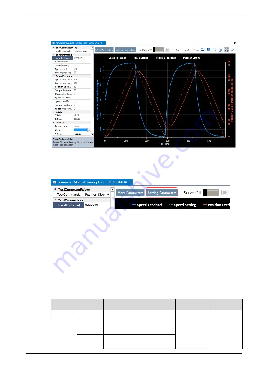
When the
Manual-Tuning Tool
function has been completed, the waveform graphics of the data result is
displayed in the window.
The figure below is an example of data collecting results with the
Position Slope
command.
Step 9
Repeat setting the parameters and perform the data collecting until result meets the requirements.
Step 10
Click
Setting Parameters
after confirming that the results have reached the desired performance, and the
parameters will be written into the Drive.
9.4
Feedback Speed Selection
The speed feedback from the encoder is the calculate result that the Drive read the position value from the
encoder and differentiate time.
There is a speed observer inside the Drive for detecting the speed of the Motor in real time. The detected
speed can be used for host controller monitoring or as a speed feedback for the speed loop.
In the case of low speed or low encoder resolution, the method of position-to-time differentiation
introduces large noise. You can set Pn162=1 to use observed speed as the feedback speed.
In addition, you can increase the setting of Pn161 for making the observed speed closer to the actual
speed, but overshooting will be likely to occur.
Parameter Setting
Meaning
When Enabled Classification
Pn161
-
Load Torque Observer Gain
Immediately
Adjustment
Pn162
0 [Default]
Use encoder speed as the feedback
speed.
After restart
Function
1
Use observed speed as the feedback
speed.


