8
INSTALLATION (CONTINUED)
INSTALLING THE VENTING SYSTEM
These models of wall furnaces are designed for direct venting through a wall.
Only venting components specifically approved for these furnaces may be used.
The flow of combustion gases and ventilation air must not be obstructed.
Minimum clearance between pipes and combustible materials is one (1) inch (25.4 mm).
Vent terminal must be 18.0” away from an adjacent wall.
Minimum clearance between vent cap and combustible material 1 ¾”.
IMPORTANT: The appliance’s venting system should be inspected at least once a year and immediately cleaned if
necessary.
IMPORTANT: THE VENT-AIR INTAKE SYSTEM MUST BE PROPERLY INSTALLED TO INSURE PROPER AND
SAFE OPERATION. THE VENT-AIR INTAKE SYSTEM MUST ALSO BE PROPERLY RE-INSTALLED AND RE-
SEALED TO INSURE PROPER AND SAFE OPERATION.
Warning:
Failure to position the parts in accordance with these diagrams or failure to use only parts specifically
approved with this appliance may result in property damage or personal injury.
Avertissement:
Risque de dommages ou de blessures si les pièces ne sont pas installées conform´ment à ces
schémas et ou si des pièces autres que celles spécifiquement approuvées avec cet appareil sont utilisées.
CAUTION: ALL JOINTS MUST BE AIR-TIGHT.
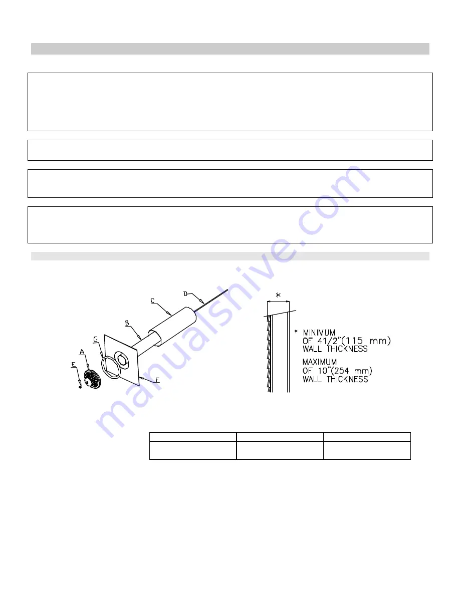
The venting system consists of: one injected-aluminum cap (A), one vent pipe (B), one vent-air intake pipe (C), one rod
(D), one nut (E), one outdoor mounting plate (F) and one silicon-rubber ring (G). (See figure 14).
Figure 14 Figure 15
1. Measure thickness of the wall as shown in figure 15.
2. If pipes (B), (C) and the rod are long, trim them according to thickness of the wall, as shown in the following table.
3. The hole at the outside of the wall must be a square of 11 ½” (290 mm) x 11 ½” (290 mm). (See figure 17).
4. From the outside of the wall, screw the rod slightly onto support located inside the appliance flue outlet.
5. Slide pipes (B) and (C) through the hole in the wall, and connect them to the appliance flue outlet and air intake,
respectively.
6. The outdoor mounting plate and the silicon-rubber ring should be installed between the vent cap and the exterior
wall. The plate must be positioned flush to the wall and with its standoffs inserted into the wall and sealed with a
non-hardening mastic (silicone caulk). (See figure 17).
Position the outdoor mounting plate so that the vent-air intake pipe has a slight downward slope to the outside.
The
downward slope is necessary to prevent the entry of rainwater.
vent pipe (B)
vent-air intake pipe (C)
Rod (D)
TABLE 3
Lengths of pipes and rod.
wall thickness
+ 3 3/8“ (86 mm)
wall thickness
+ 2 1/2“ (64 mm)
wall thickness
+ 5 7/8“ (149.5 mm)
Содержание DVEL 12
Страница 13: ...12 OPERATION CONTINUED Pilot Burner...
Страница 14: ...13 POUR COUPER L ADMISION DE GAZ DE L APPAREIL Veilleuse ALLUMAGE...
Страница 20: ...19 Model DVEL 8 19...
Страница 21: ...Model DVEL 12 20...
Страница 22: ...Model DVEL 20 21...


