


Hardware Installation
IMPORTANT
The CAN-PCI104/200-2 (module with 2 CAN-interfaces) only uses one interrupt on
the PCI-Bus as well.
Set the position of the coding switch before you mount the CAN-PCI104/200 because it might
be difficult to access the coding switch when the module is mounted.
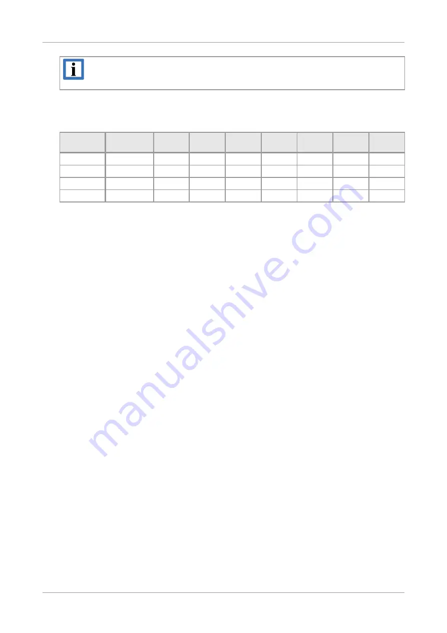
Position of
coding switch
PCI-104-stack
number
REQ#
GNT#
CLK
INT0#
INT1#
INT2#
INT3#
0, 4, 8, C
1
REQ0#
GNT0#
CLK0
INTA#
INTB#
INTC#
INTD#
1, 5, 9, D
2
REQ1#
GNT1#
CLK1
INTB#
INTC#
INTD#
INTA#
2, 6, A, E
3
REQ2#
GNT2#
CLK2
INTC#
INTD#
INTA#
INTB#
3, 7, B, F
4
REQ3#
GNT3#
CLK3
INTD#
INTA#
INTB#
INTC#
Table 1:
Setting the simulated PCI-slot with coding switch SW130
Install the CAN-PCI104/200 on the PCI-104 stack position you have selected.
6.
Close the computer case again.
7.
Connect the CAN wire.
Please note that the CAN bus must be terminated at both ends.
Additionally, the CAN_GND must be connected to earth at exactly one point in the CAN
network. Use the special T- connectors and terminator connectors offered by esd.
A CAN device whose CAN interface is not electrically isolated acts as an earth connection
like the CAN_GND.
Please pay attention to the notes on correct wiring of CAN networks (see from page 25)!
The CAN-bus interfaces with the ISO11898-2 compliant signals have to be connected to the
pin post connectors X400 (CAN 0) and X410 (CAN 1, only equipped in the 2x CAN versions).
8.
Connect the computer to mains again (mains connector or safety fuse).
9.
Switch on the computer, the peripheral devices and the other CAN devices again.
10. End of hardware installation.
11. Set the interface properties in your operating system.
Continue with the software installation as described in the manual ‘NTCAN-API, Installation
Guide’.
CAN-PCI104/200
Hardware Manual • Doc. No.: C.2046.21 / Rev. 1.1
Page 11 of 29


