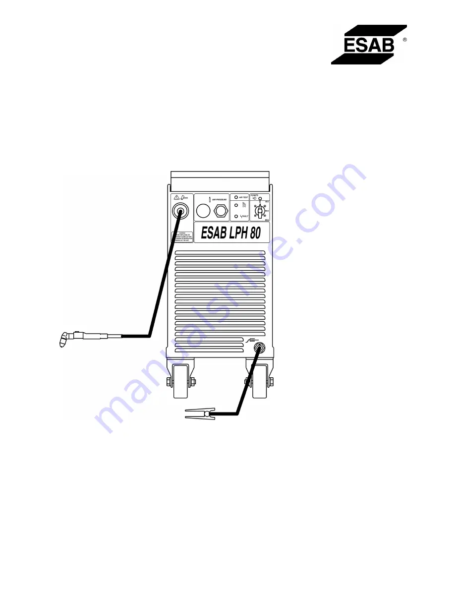
background image

LPH 80

Bruksanvisning
Brugsanvisning
Bruksanvisning
Käyttöohjeet
Instruction Manual
Betriebsanweisung
Manuel d’instructions

Gebruiksaanwijzing
Instrucciones de uso
Instruzioni per l’uso
Manual de instruções

Οδηγίες


χρήσεως

Instrukcja obs

ł

ugi

0349 30

1

 028

0

1

0320

Valid for serial no. 

11

2-xxx-xxxx

Содержание LPH 80

Страница 1: ...uksanvisning K ytt ohjeet Instruction Manual Betriebsanweisung Manuel d instructions Gebruiksaanwijzing Instrucciones de uso Instruzioni per l uso Manual de instru es Instrukcja obs ugi 0349 301 028 0...

Страница 2: ...T REQUIRED 47 4 3 LOCATION 47 4 4 INSPECTION 47 4 5 AIR LINES CONNECTIOINS 47 4 6 PRIMARY ELECTRICAL CONNECTIONS 47 4 7 SECONDARY CONNECTIONS 48 5 OPERATION 50 5 1 GENERAL 50 6 MAINTENANCE 51 6 1 CLEA...

Страница 3: ...ent such as goggles non flammable clothing protective gloves never wear loose clothing belts bracelets rings etc which may catch on equipment or cause burns Miscellaneous only authorised personnel may...

Страница 4: ...head away from fumes Use ventilation and or extraction to keep fumes and gases away from your breathing zone and surroundings ARC RAYS Can injure eyes and burn skin Protect your eyes and skin Use corr...

Страница 5: ...NICAL DATA Rated 60 Duty Cycle 80A Output 100 Duty Cycle 40A 60A Output Current Range 40 80A Open Circuit Voltage 310V Rated primary input max 400 415V 3 50 60Hz 29A phase Air Requirements PT 27 118 l...

Страница 6: ...ify transporters of any defects or damages at once B Check container for any loose parts before disposal C Check air louvers and any other openings to make sure any obstruction is removed 4 5 AIR LINE...

Страница 7: ...connected from mains by unplugging power cable opening switchboard switch or opening disconnect switch 1 Connect air supply line to inlet of regulator 2 Clamp work cable to workpiece Make sure the wor...

Страница 8: ...49 Fig 4 2 Ground and current cable connections...

Страница 9: ...om lines D FAULT LIGHT Will glow yellow under following conditions FLOW FAULT Indicates too low air flow rate continuous light only when el valve opened OVER TEMPERATURE Indicates that duty cycle has...

Страница 10: ...lly useful in helping to create a drop cut When not using the standoff guide the nozzle should be held approximately 2 3 mm from the work E When ending a cut the torch switch should be released and li...

Страница 11: ...worn electrode B Main arc extinguishes 1 Cutting speed too slow 2 Worn electrode F Unstable cutting conditions 1 Incorrect cutting speed 2 Lose cable or hose connections 3 Electrode and or nozzle in p...

Отзывы: