Chapter 2
HARDWARE INSTALLATION
User's Manual
20
SB
T
X
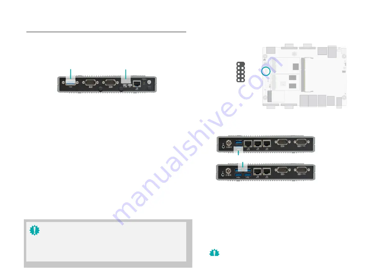
I/O Ports
USB Ports
Graphics Display
10
N.C
.
GN
D
+Data
-Data
VCC
2 1
Key
GN
D
+Data
-Data
VCC
Front Panel
USB 6/7
(USB
2.0)
HDMI
The HDMI port which carries both digital audio and video signals is used to connect a LCD monitor
or digital TV that has the HDMI port.
Displ+
The DisplayPort (DP) is a digital display interface used to connect a display device such as a
computer monitor. It is used to transmit audio and video simultaneously. The interface, which is
developed by VESA, delivers higher performance features than any other digital interface. DP++
is supported by the system board for converting to DVI and HDMI signals.
VGA
Rear Panel
(4 x LAN, 2 x USB)
(2 x LAN, 4 x USB)
The VGA port is used for connecting a VGA monitor. Connect the monitor’s 15-pin D-shell cable
connector to the VGA port. After you plug the monitor’s cable connector into the VGA port, gen-
tly tighten the cable screws to hold the connector in place.
USB allows data exchange between your computer and a wide range of simultaneously acces-
sible external Plug and Play peripherals. The system board is equipped with multiple USB Type
A ports at the front panel — two USB 3.0 or four USB 3.0 ports — along with two internal USB
2.0 pin-header ports.
Wake-On-USB Keyboard/Mouse
The Wake-On-USB Keyboard/Mouse function allows you to use a USB keyboard or USB mouse
to wake up a system from the S3 (STR - Suspend To RAM) state.
BIOS Setting
Configure USB devices in the Advanced menu (“USB Configuration” submenu) of the BIOS. Re-
fer to Chapter 7 for more information.
Important:
The USB 2.0 header can be optional removed in stock settings to transmit USB 7
U
pe A
VGA or
HDMI/DP
Important:
Please be cautious when inserting an HDMI cable into the HDMI/DP port. The HDMI
male connector shall align to the left of the port as illustrated here. The insertion is
fairly effortless and please reframe from forcing the insertion to pre- vent damage.
10
1
11
2
12
3
10
1
2 6
2 1
1 5


