AUTOMATIC SWING DOOR
INSTALLATION GUIDE
www.erreka.com
PREMIS 200
Страница 1: ...AUTOMATIC SWING DOOR INSTALLATION GUIDE www erreka com PREMIS 200...
Страница 2: ......
Страница 3: ...________________ 21 Pull slide arm APR01 installation _____________________________ 21 Push articulated arm APR02 installation _______________________ 23 Operator adjustments door close mode _________...
Страница 4: ...anual The manufacturer s complete address is indicated on the back cover of this manual The model or type of the actuator reference is indicated in the Operator characteristics section of this manual...
Страница 5: ...are indicated in the Installation chapter of this manual If you install protective devices not supplied with this device refer to the instructions for those components Details on how to regulate the c...
Страница 6: ...ents or failures The installer shall be responsible for ensuring the installation is set up for its envisaged use 4 INSTALLER S QUALIFICATIONS Installation should be completed by a professional instal...
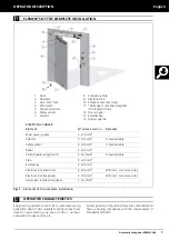
Страница 7: ...andard EN 16005 ELECTRICAL CABLES Element N wires x section Remarks Main power supply 3 x 1 5mm2 Selector 4 x 0 5mm2 Screened cable Safety sensor 6 x 0 5mm2 Screened cable Radar 4 x 0 5mm2 CAN Double...
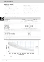
Страница 8: ...racteristics of the operator Operation diagram If it is necessary parameters must be adjusted in each installation CHARACTERISTIC PREMIS200 PREMIS200M Dimensions Operator 644x75x138 mm Power supply V...
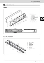
Страница 9: ...l slide arm APR01 1 Cover 2 Bracket profile 3 Control plate 4 Power plate 5 Spring force regulator 6 Side switch 7 Limit micro switch 8 Reduction unit 9 Motor 10 Side plastic cover 11 Side reset butto...
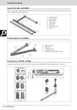
Страница 10: ...ghts relative to the door 1 Acoplamiento eje 2 Brazos especiales 3 Perfil gu a 4 Taco gu a 5 Tope final de carrera 6 Embellecedor lateral 7 Eje Taco gu a 8 Calzo distanciador 1 Shaft coupling 2 Specia...
Страница 11: ...re should be no stiffness throughout its open close Ambient conditions This device is not suitable for installation in inflammable or explosive environments Check that the admissible ambient temperatu...
Страница 12: ...nt deformation If the wall where the operator is to be secured is not strong and reliable a drilled metal plate can be provided on request to 36 37 38 14 15 1 Remove the screws from the cover and extr...
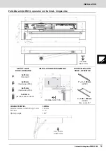
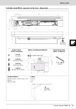
Страница 13: ...Distance between shafts hinge arm EN Class Opening angle SWING 205 mm 4 6 100 X 25mm Standard X 50mm Standard APR03 X 75mm Standard APR04 X 100mm Standard APR03 APR04 Y 0 100mm APR01 Y 100 250mm APR0...
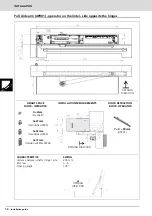
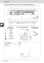
Страница 14: ...s CHARACTERISTICS Distance between shafts hinge arm EN Class Opening angle SWING 205 mm 4 6 100 X 2mm Standard X 27mm Standard APR03 X 52mm Standard APR04 X 77mm Standard APR03 APR04 Y 0 90mm APR01 HE...
Страница 15: ...e CHARACTERISTICS Distance between shafts hinge arm EN Class Opening angle SWING 205 mm 4 6 90 X 5mm Standard X 30mm Standard APR03 X 55mm Standard APR04 X 80mm Standard APR03 APR04 Y 0 35mm APR01 HEI...
Страница 16: ...CHARACTERISTICS Distance between shafts hinge arm EN Class Opening angle SWING 205 mm 3 6 100 X 25mm Standard X 50mm Standard APR03 X 75mm Standard APR04 X 100mm Standard APR03 APR04 Y 0 35mm APR01 HE...
Страница 17: ...the hinges CHARACTERISTICS Distance between shafts hinge arm EN Class Opening angle SWING 205 mm 4 6 100 X 2mm Standard X 27mm Standard APR03 X 52mm Standard APR04 X 77mm Standard APR03 APR04 Y 0 210m...
Страница 18: ...RACTERISTICS Distance between shafts hinge arm EN Class Opening angle SWING 205 mm 4 6 100 X 5mm Standard X 30mm Standard APR03 X 55mm Standard APR04 X 80mm Standard APR03 APR04 Y 0 165mm APR02 HEIGHT...
Страница 19: ...ges side CHARACTERISTICS Distance between shafts hinge arm EN Class Opening angle SWING 205 mm 4 6 95 X 25mm Standard X 50mm Standard APR03 X 75mm Standard APR04 X 100mm Standard APR03 APR04 Y 100 250...
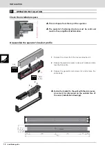
Страница 20: ...he intermediate casing must remain attached Make holes in the side covers to pass cables from one operator to another X Distance between operators 1 Operator 1 cover 2 Operator 2 cover 3 Intermediate...
Страница 21: ...n cables in the control board 7 PULL SLIDE ARM APR01 INSTALLATION Installing the guide profile On the door On the lintel 1 Insert the Guide block with its shaft inside the profile 2 Insert the stopper...
Страница 22: ...th the door closed 3 Turn the arm in the door s OPENING DIRECTION and lock the geared motor with the locking piece 4 Release the arm and fasten the arm in the position it will be in with the door clos...
Страница 23: ...the door closed 2 Turn the arm in the door s OPENING DIRECTION and lock the geared motor with the locking piece 3 Release the arm Fasten the arm again in the position it will be in with the door close...
Страница 24: ...e to work A microswitch can be inserted in the operator so motor braking can be disabled at the end of closing and the door closes with more force Adjust the part 3 to enable the microswitch 4 in the...
Страница 25: ...tting the cover on Try to pass the cables through zone 1 If necessary they can also be passed through zone 2 Take care when installing cables in spaces with little room Once ordered securing the cable...
Страница 26: ...THE SWITCH 1 is in the correct position according to the mains supply MAINS POWER N P E L SWITCH ON OFF SWITCH 230V 115V TRANSFORMER PRIMARY TRANSFORMER SECONDARY OUTPUT ELECTRONIC PLATE FUSE 4A 5X20...
Страница 27: ...ELECTROLOCK SIDE SWITCH DIGITAL SELECTOR DIRECTION MOTOR BRAKE ENCODER CONNECTOR MOTOR CONNECTOR MOTOR BRAKE ON OFF LEVEL MOTOR BRAKE SYNCHRONISATION POWER SUPPLY UNIT MICROPROCESSOR RESET MANUAL SELE...
Страница 28: ...eously pressing for 3 sec The door carries out an automatic reset To lock the selector press the keys for 3 sec Repeat the sequence to unlock When the selector is locked the screen shows the icon Manu...
Страница 29: ...concealed pushbutton to the right of the exit only icon using a tipped instrument It is not possible to configure any door parameters with the rotary selector SET UP Press RESET for 5 sec LED Normal...
Страница 30: ...the sensors must be installed on the Master board Safety sensors Closing surveillance Fit the sensor SIS on the door When the sensor is enabled in the closing movement the door stops and reverses at n...
Страница 31: ...been carried out the operator will return to the previous operating mode Closing impulse function KC This input leads the operator to close the door in night mode Selectors and programmable inputs ar...
Страница 32: ...s is the type of signal the electrical lock uses to indicate its status NA NC OFF test disabled In order to guarantee safe operation of the drive unit the locking device must meet the following specif...
Страница 33: ...anual Digital selector DIG SEL02 Rotary selector ROT SEL01 Install the Digital selector or Rotary selector according to the following connections diagram Side switch Connect the side switch cables acc...
Страница 34: ...ing programmable inputs can be configured from the selector Disabled unconfigured input Single direction Partial Door open Door closed Manual Automatic Stop Courtesy opening for the disabled Emergency...
Страница 35: ...gnal will be normally open Programmable input HOLD OPEN A programmable input can be configured to keep the door open using the hold open devices In this case the door is only kept open by the action o...
Страница 36: ...mable outputs can be configured from the selector Disabled unconfigured output Ding dong Door Open Anti tampering Door Closed Warning Toilet engaged more information on page 36 Toilet free more inform...
Страница 37: ...with the basic parameters of the doors for a correct use First the Master door the operator which starts the movement and then the Slave When it is necessary to modify other parameters it is necessary...
Страница 38: ...e operator which starts the movement and then the Slave When it is necessary to modify other parameters it is necessary to enter the USER and SAT menus of each Sliding operator Master 1 Slave 1 Master...
Страница 39: ...uguese 1 2 6 Basque 1 2 7 Polish 1 3 Information 1 3 1 General Commission Date Define the operator s location Type of opener Define how is works the operator Low Energy FE Normal FE Firewall Serial n...
Страница 40: ...y in order to comply with the standards No additional safety sensors are required they are optional Protection of the secondary closing edge should be considered separately Full Energy default value N...
Страница 41: ...magnet Continuous power supply device During opening the operator stops powering the lock starting to open after a while During closing the operator does not power the lock During door closed the ope...
Страница 42: ...le Disable To enable or disable the interlock Type of interlock Normal Interlock default value Smart Interlock NORMAL INTERLOCK the master operator 2 does not open even if the interior or exterior act...
Страница 43: ...n closing direction Use ONLY KI KA inputs for SEMI AUTOMATIC Accessible toilets TOILET INGRESS if the toilet is vacant green status indicator the door opens automatically when the external opening but...
Страница 44: ...e In manual mode the door works as a normal door closer OPENING the door opens manually STANDBY no standby time CLOSING the compression spring closes the door Servo assisted 0 to 5 default value 0 The...
Страница 45: ...sary to re enable the operator Hold Open Mode When the hold open signal is enabled the door switches to open When it reaches Door Open the operator powers the fastening devices and the motor is releas...
Страница 46: ...d default Activa tion NO default value Normally Open Output Signal NC Normally Closed Output Signal Side switch with in puts 3 4 in Disa bled mode Door Open default value The door goes to Door Open mo...
Страница 47: ...Semi automatic Exterior Configuration NO default value NC Disabled Activation valid for modes AUTOMATIC INGRESS ONLY SEMI AUTOMATIC AND INTERLOCK NO Input Normally Open default setting NC Input Normal...
Страница 48: ...0 sec default value 10 Increasing the value decreases closing movement speed with motor Courtesy activation Slow Speed 1 to 5 default value 3 Door speed in anti crushing movement Acceleration 0 to 5 d...
Страница 49: ...isables this function default setting Increasing the value increases the impulse intensity re quired to release the motor Disabling this function and configuring motor close to guarantee controlled mo...
Страница 50: ...out on Disables the maintenance required warning Password Change password Changes the password for the Technical Menu Reset password Resets the password to 00000 Enable password Disabled default valu...
Страница 51: ...INSTALLATION DOOR CONFIGURATION Automatic swing door PREMIS 200 51 Power diagram Opening direction diagram 1 Door closed 2 Spring assistance 3 Spring assistance position 4 Start spring closing 5 Fina...
Страница 52: ...not too tight in the strike Poor configuration Check the configuration type and voltage Configure the following to improve electrolock release Opening Delay configure a delay so the electrolock has t...
Страница 53: ...acle in the photocell detection area Check the proper operating of the photocell if it works properly remove the obstacle A reset could be done for a quick recovery Warning 9 Remote safety closing ena...
Страница 54: ...hnical support a replacement of the photocell could be necessary Temporally a configuration normally closed without test could be used Warning 26 Remote photocell test failure Photocell damaged Check...
Страница 55: ...ication wire is installed correctly Make a reset to recover the proper functionality If the warning persists check the configuration of the boards Warning 35 Incomplete reset The opener cannot make a...
Страница 56: ...s again with the spring at controlled speed without any danger Remove the main power line before starting operations on the operator Any component that is damaged or worn must be replaced Use only ori...
Страница 57: ...7 77 Fax 93 729 07 93 puertas catalunya erreka com ERREKA NOROESTE Menendez Pelayo 7 bajo derecha 36202 Vigo Pontevedra Tel 986 205 102 Fax 986 296 602 puertas noroeste erreka com ERREKA LEVANTE Parqu...
Страница 58: ...Erreka B Ibarreta s n 20577 Antzuola Gipuzkoa T 943 786 150 F 943 787 072 info erreka com www erreka com MSY 002 03...