background image

7

<<<

<<<

ENGLISH

<<<

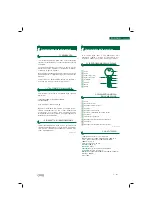
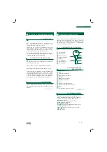
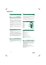
2.4.2 Electric circuit

The main components of the electric circuit and 
the electronic components are as follows:

1
2
3
4

Socket
Start switch
Motor
Microswitch

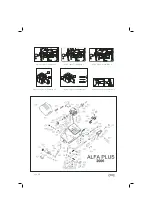
See Figure 4

4
5

1
2

3

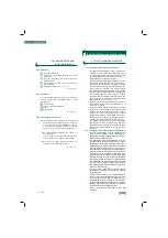
Size 18 spanner
Keys to adjust the height and depth of the 
teeth.
Wedges to adjust the tip of the key.
Recessed wedges to cut cross-shaped keys.
Set of allen keys (2, 2.5, 3, 4, 5).

See Figure 3

2.4.1 Accesories

2.4.3 4-sided clamp 

The clamp is designed to secure a different family 
of keys on each side. The figure shows the possibi-
lities for cutting on each side of the clamp.

1)

 Cutting the key with support on the back:

    Side 1: Keys with normal blade
    Side 2: Keys with narrow blade

2)

 Cutting by means of clamping the key by the 

guide (profile).

See Figure 5

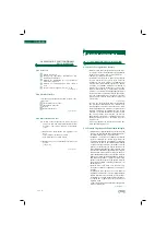
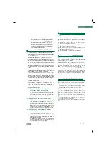
3.1.1 Control and adjustment of the side distance

 Place the two adjustment keys (1) in the clamps, so 

that the head of the adjustment key rests against 
the inner stop of side 1 or 2 of the clamp.

 Then tighten the clamps.

 Move the clamps with the adjustment keys (1) 

towards the tracer point (I) and the milling cutter 
(F), so that the adjustment keys are in the correct 
position in respect of the tracer point and milling 
cutter. This is done by moving the slide backwards 
and keeping it in that position with the help of the 
handle (M), moving the slide to the right with the 
help of the arm (B), thereby releasing the slide, and 
then moving the slide gently over the tracer point 
(I) and milling cutter (F). 

(See Figure 6)

 If the grooves of the adjustment key do not coincide 

properly with the tracer point and the milling cutter, 
proceed as follows:

 By gently loosening the shaft screws (T), you will be 

able to move the milling cutter to the right or left. 
You have to move the milling cutter to a position in 
which it coincides with the groove of the correspon-
ding adjustment key. To carry out this operation, you 
have to remove the motor guard first.

 The distance is now perfectly adjusted, with the tracer 

point and milling cutter coinciding with the respective 
recesses of the adjustment keys. Now tighten the 
shaft screws (T).

3.1.2 Control and adjustment of the cutting depth

• 

Place the two adjustment keys (1) in the clamps, so 

that the head of the adjustment key rests against 
the inner stop of side 1 or 2 of the clamp.

• 

Move the clamps with the adjustment keys (1) 

towards the tracer point (I) and the milling cutter (F), 
so that the adjustment keys rest on the tracer point 
and the milling cutter. The machine slide can be 
released in the following way: move the slide bac-
kwards and keeping it in that position with the help 
of the lever (M), move the slide to the right, with the 
help of the arm (B). To lock the slide again, reverse 
the process, with the slide midway along its travel. 
Move the slide back with the help of the handle (M) 
and keeping it in that position, move the slide to the 
left with the help of the arm (B). With the slide as far 
to the left as possible, gently release the slide so that 
it becomes locked.

• 

Turn the milling cutter by hand. If it gently rubs the 

adjustment keys, the machine is properly adjusted.

 If the milling cutter turns freely, without rubbing, 

this indicates that it is to far back in respect of the 
tracer point and is not cutting deeply enough. On 
the other hand, if the milling cutter becomes jam-
med up against the adjustment key, this indicates 
that it is too far forward in respect of the tracer point 
and is cutting too deeply.

 If either of these situations should occur, proceed 

as follows:

 - 

Undo the screw (L) securing the tracer point (I) and   

turn the micrometric screw (H). 

See Figure 7.

How the machine works

3.1 MACHINE ADJUSTMENT

3

2.4 COMPONENTS AND

FUNCTIONAL PARTS

NOTE: WHEN YOU PLUG THE MACHINE, YOU HAVE TO 
SWITCH ON THE SEGURITY SYSTEM,. THIS IS MADE BY 
MOVING THE BASE OF THE CLAMP.

Содержание ALFA PLUS

Страница 1: ...UINA DUPLICADORA ALFA PLUS Manual de instru es M QUINA DUPLICADORA ALFA PLUS Manual de instrucciones MACCHINA DUPLICATRICE ALFA PLUS Manuale d istruzione KEY CUTTING MACHINE ALFA PLUS Instruction manu...

Страница 2: ...12 4 1 Fr serwechsel 12 4 4 Sicherheitsempfehlungen 12 5 Abbildung 21 22 Inhaltsverzeichnis 1 Presentation et aspects generaux 12 1 1 Generalites 12 1 2 Transport et emballage 12 1 3 Plaque signaleti...

Страница 3: ...regolazione La macchina si presenta in un imballo delle seguenti dimensioni Larghezza 570mm lunghezza 520mm altezza 410mm Peso macchina imballo 20 kg Quando si disimballa la macchina si consiglia di...

Страница 4: ...bisogna procedere nel seguente modo allen tando leggermente la pressione sui grani T del supporto abbiamo la possibilit di spostare la fresa a destra o a sinistra Dobbiamo spostare la fresa fino a un...

Страница 5: ...ntenere sempre pulita la macchina Lavorare sempre con le mani asciutte Bisogna usare occhiali di protezione Assicurarsi che la macchina abbia la presa di terra 3 2 1 Duplicazione della chiave con cann...

Страница 6: ...mm length 520 mm height 410mm Machine weight plus packing 20 Kg When the machine has been unpacked check carefully to see if it has suffered any damage during transporta tion If you find any problems...

Страница 7: ...roove of the correspon ding adjustment key To carry out this operation you have to remove the motor guard first The distance is now perfectly adjusted with the tracer point and milling cutter coincidi...

Страница 8: ...hat the machine is earthed 3 2 1 Cutting keys with narrow blades Side 2 of the clamp To cut this type of key and so that the milling cutter reaches the maximum cutting depth side 2 of the clamp must b...

Страница 9: ...u verwen denden Werkzeuge vorzunehmen sind Die Maschine wird in einer Verpackung mit folgenden Abmessungen ausgeliefert Breite 570 mm L nge 520 mm H he 410mm Maschinengewicht zus tzlich Verpackung 18...

Страница 10: ...achrechtsoderlinks gefahren werden Der Fr ser mu so lange verfahren werden bis er eine Stellung erreicht in der er mit der entsprechenden Nut des Einstellschl ssels bereins timmt Um diesen Vorgang dur...

Страница 11: ...gsdieKeilezuentfernen 3 2 3 Kopieren von kreuzf rmigen Schl sseln Seite 1 der Spannbacke Diese Schl sselart mu von links nach rechts in die Spannbacken eingef hrt werden Die Keile 5 siehe Abbildung Nr...

Страница 12: ...our utilisation et ne demande que des op rations d talonnage des outils utiliser La machine se pr sente dans un emballage aux dimen sions suivantes Largeur 570 mm longueur 520 mm hauteur 410 mm Poids...

Страница 13: ...l y a la possibilit de d placer la fraise droite ou gauche Il faut d placer la fraise pour la faire co ncider avec l entaille de la cl de r glage correspondante Cette op ration se r alise apr s avoir...

Страница 14: ...propres Travailler avec les mains s ches Utiliser des lunettes de protection m me si la machi ne dispose de protections S assurer que la prise lectrique dispose d une prise de terre 3 2 1 Reproduction...

Страница 15: ...ular a m quina sem ler primeiro este manual A m quina sai da nossa f brica pronta para ser utilizada e apenas requer opera es de calibra o para as ferra mentas que vai utilizar A m quina apresenta se...

Страница 16: ...sa para a direita ou para a esquerda Devemos deslocar a fresa para uma posi o na qual coincida com o entalhe da chave de afina o correspondente Para realizar esta opera o necess rio soltar previamente...

Страница 17: ...za Mantenha a fresa limpa e livre de aparas assim como a zona de apoio das morda as para que estas n o se danifiquem Mantenha sempre limpa quer a m quina quer o espa o em volta Trabalhe com as m os se...

Страница 18: ...guientes Ancho 570 mm larga 520 mm alto 410mm Peso m quina m s embalaje 20 Kg de peso Cuando desembale la m quina inspeccione cuidado samente por si hubiese sufrido alg n da o en el trans porte Si enc...

Страница 19: ...el eje tenemos la posibilidad de desplazar la fresa a derecha o izquierda Debemos desplazar la fresa hasta una posici n en la cu l coincida sobre la muesca de la llave de reglaje correspondiente Para...

Страница 20: ...ado de este tipo de llave y con el fin de que la fresa alcance el m ximo de profundidad en el corte se va utilizar el lado 2 de la mordaza que nos per mite una profundizaci n mayor a la hora de duplic...

Страница 21: ...2 3 4 Figura 1 Figure 1 Abbildung 1 Figura 2 Figure 2 Abbildung 2 Figura 3 Figure 3 Abbildung 3 1 2 3 4 M Fuses 0 1 Figura 4 Figure 4 Abbildung 4 Standard Portugal Figura 5 Figure 5 Abbildung 5 8 10...

Страница 22: ...C T H L B M 4 4 2 F I M C B 3 3 1 Figura 6 Figure 6 Abbildung 6 Figura 7 Figure 7 Abbildung 7 Figura 8 Figure 8 Abbildung 8 Figura 10 Figure 10 Abbildung 10 Figura 11 Figure 11 Abbildung 11 F K R Figu...

Страница 23: ......
Страница 24: ...42 49 32040 Cibiana di Cadore BL Italy Tel 39 0435 542500 Fax 39 0435 542522 Email info errebispa com www errebispa com ERREBI DEUTSCHLAND GmbH Neustrasse 161 42553 Velbert Germany Tel 02053 49620 Fax...

Отзывы: