


EG_GenLoc54e_1040_UG_002_UK
Page 20 / 86
Descriptions and non-contractual illustrations in this document are given as an indication only.
ERCOGENER reserves the right to make any modifications.
Dct_427_02
3.2 External connections
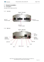
3.2.1
Connections
3.2.1.1
Antenna connectors
GSM antenna connector:
The GSM antenna connector is FAKRA D male with a 50Ω impedance.
GPS antenna connector:
The GPS antenna connecto
r is FAKRA C male with a 50Ω impedance.
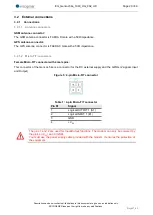
3.2.1.2
Micro FIT connectors
Female Micro-FIT connector with 4 male pins:
This connector of the GenLoc 54e is a connector for the DC external supply and the GPIOs (2 signals Input
and Output).
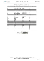
Figure 5 : 4-pin Micro-FIT connector
Table 1 : 4-pin Micro-FIT connector
Pin N°
Signal
1
Logical OUTPUT 1 (S1)
2
Logical INPUT 1 (E1)
3
GND
4
+V
DC
The pins 1 and 2 are used for Input/Output functions. The modem can only be powered by
the pins 4 (+V
DC
) and 3 (GND).
You must use the power supply cable provided with the modem. It ensures the protection of
the equipment.


