


40
Connecting the Peripherals
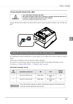
Connecting the Cash Drawer
Specifications of drawers differ depending on makers or models. When you use a drawer other than specified,
make sure its specification meets the following conditions.
Otherwise, devices may be damaged.
The load, such as a drawer kick solenoid, must be connected between pins 4 and 2 or pins 4 and 5 of the
drawer kick connector.
When the drawer open/close signal is used, a switch must be provided between drawer kick connector pins 3
and 6.
The resistance of the load, such as a drawer kick solenoid, must be 24
or more or the input current must be
1A or less.
Be sure to use the 24V power output on drawer kick connector pin 4 for driving the equipment.
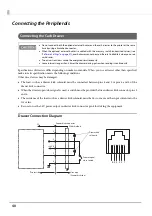
Drawer Connection Diagram
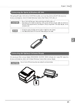
Do not connect both the optional external buzzer and the cash drawer to the printer at the same
time by using a branched connector.
When the optional external buzzer is enabled with the memory switch (customized values) (see
"Software Settings" on page 57
), a cash drawer cannot be used. Be sure to disable it when you use a
cash drawer.
Two driver transistors cannot be energized simultaneously.
Leave intervals longer than 4 times the drawer driving pulse when sending it continuously.
F.G
+24V
6 5 4 3 2 1
With shielded
Drawer kick connector
Printer side
User side
[Drawer kick side]
Drawer open/
close switch
Drawer kick
solenoid
1
2
3
4
5
6
Содержание TM-T88VI-iHUB
Страница 11: ...11 Procedure 143 Changing the Bluetooth Low Energy Technology Advertising Packet 144 Character Code Tables 155 ...
Страница 12: ...12 ...
Страница 54: ...54 ...
Страница 113: ...113 Chapter 5 Handling 5 5 Tear off the paper ...
Страница 115: ...115 Chapter 5 Handling 5 3 Remove the jammed paper 4 Close the covers ...
Страница 122: ...122 ...
Страница 133: ...133 Appendix Units mm ...
Страница 136: ...136 Italian Spanish English UK Keyboard type Key layout ...
Страница 156: ...156 ...


