background image

EPSON Stylus Pro 7400/7800/9400/9800

Revision B

Operating Principles

Print Mechanism Components

153

PLATEN GAP ADJUSTMENT UNIT

In order to maintain the print precision, it is necessary to maintain the carriage (= head) 
mounting position so that it is always a constant distance from the surface of the paper.
In this printer, the print head nozzle surfaces and platen surface are variable 
mechanisms so that the gap between the paper printing surface and the head nozzle 
surface can be kept constant. 
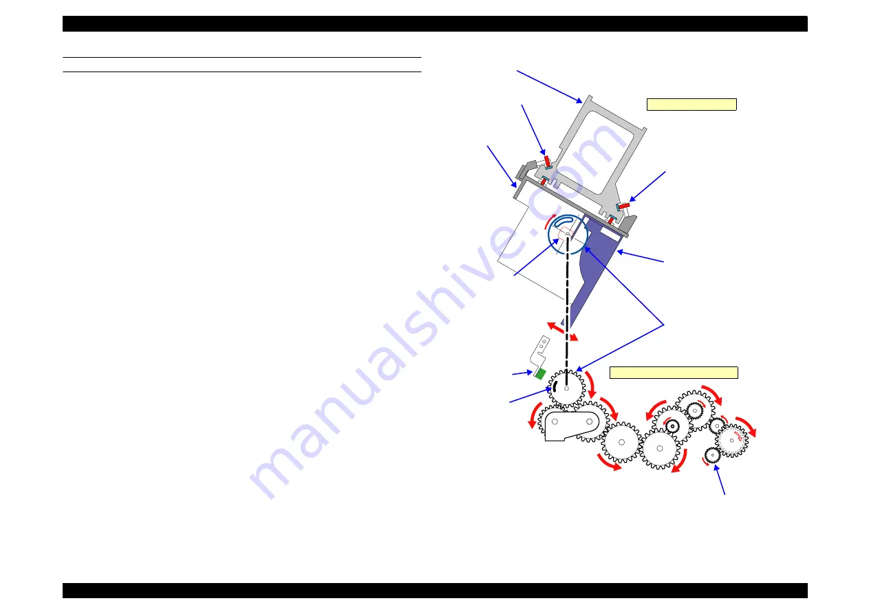
The carriage has a 2-body construction with a sub-carriage on which the print heads are 
mounted attached to the carriage which forms the base. The sub-carriage moves in the 
vertical direction with respect to the paper surface. This movable system uses a cam (= 
PG). When the sub-carriage is in the HP position (= right end), the pump motor and the 
gear mounted on the cam shaft engage, the motor’s rotation (reverse) drives the cam 
and the sub-carriage is positioned at the proper gap position. 
In order to maintain the distance between the print head nozzle surface and the paper 
properly, the thicknesses of the paper used are classified into 5 levels for PG setting, 
namely, minimum PG (0.8 mm), small PG (1.2 mm), medium PG (1.6mm), large PG 
(2.1 mm), and maximum PG (2.6 mm). 
The sensors used in the platen gap adjustment unit are explained below.

Figure 2-3. Carriage Mechanical Unit and PG Adjustment Unit

Slide Gear

Sub-carriage (Head Mounted)

Bearing (Roll Type)

CR Guide Rail

Carriage

PG (Head SLID)

Right Side of Carriage

Bearing (Roll Type)

PG HP Sensor

HP Detection 
Flag

Pump Motor Drive Force 
(CCW)

Right Side of Printer Mechanism

Содержание Stylus Pro 7400

Страница 1: ...EPSONStylusPro7400 7800 9400 9800 Large Format Color Inkjet Printer SERVICE MANUAL SEIJ05002 ...

Страница 2: ...f this manual However should any errors be detected SEIKO EPSON would greatly appreciate being informed of them The above not withstanding SEIKO EPSON CORPORATION can assume no responsibility for any errors in this manual or the consequences thereof EPSON is a registered trademark of SEIKO EPSON CORPORATION General Notice Other product names used herein are for identification purpose only and may ...

Страница 3: ...E POWER SUPPLY CABLE MUST BE CONNECTED USE EXTREME CAUTION IN WORKING ON POWER SUPPLY AND OTHER ELECTRONIC COMPONENTS WARNING 1 REPAIRS ON EPSON PRODUCT SHOULD BE PERFORMED ONLY BY AN EPSON CERTIFIED REPAIR TECHNICIAN 2 MAKE CERTAIN THAT THE SOURCE VOLTAGES IS THE SAME AS THE RATED VOLTAGE LISTED ON THE SERIAL NUMBER RATING PLATE IF THE EPSON PRODUCT HAS A PRIMARY AC RATING DIFFERENT FROM AVAILABL...

Страница 4: ... servicing the product APPENDIX Provides the following additional information for reference Connector pin assignments Electric circuit boards components layout Electrical circuit boards schematics Exploded diagram Parts List Symbols Used in this Manual Various symbols are used throughout this manual either to provide additional information on a specific topic or to warn of possible danger present ...

Страница 5: ...er Cleaning Page 94 CAUTION in Edge Sensor Level Measurement Page 112 has been deleted Chapter 2 Made changes in 2 2 4 Cleaning Mechanism Page 163 2 5 Colorimetric Calibration Color ID Overview Page 169 has been added Chapter 4 ADJUSTMENT REQUIRED has been added in 4 2 4 2 P S BOARD ASSY Page 234 ADJUSTMENT REQUIRED has been added in 4 2 4 4 BOARD ASSY SUB Page 236 Made changes and added REASSEMBL...

Страница 6: ...Made changes in 5 3 8 Print Head Slant Adjustment PF Page 322 Made changes in 5 3 9 Print Head Slant Adjustment CR Page 325 Made changes in 5 3 10 Ink Mark Sensor Level Adjustment Page 328 Made changes in 5 3 11 Auto Uni D Adjustment Page 329 Made changes in 5 3 12 Auto Bi D Adjustment P G 0 8 1 6 Page 330 Made changes in 5 3 13 Ink Mark Sensor Adjustment for Auto Nozzle Check Page 331 Made change...

Страница 7: ...Controller 138 1 6 Interface 139 1 6 1 USB interface 139 1 6 2 IEEE1394 Interface 140 1 6 3 Optional Interface 141 1 6 4 Received Buffer Full Operation 143 1 6 5 Interface Selection 143 1 7 Optional Units and Consumables 144 1 7 1 Ink Cartridge 144 1 7 2 Cleaning Cartridge 145 1 7 3 Conversion Cartridge 145 1 7 4 Maintenance Tank 146 Chapter 2 Operating Principles 2 1 Overview 148 2 2 Print Mechan...

Страница 8: ... Serial Number 315 5 3 4 T B S Roll Paper 316 5 3 5 T B S 980mm Band Feed 318 5 3 6 Cutter Pressure Adjustment 320 5 3 7 Nozzle Bi D Adjustment 321 5 3 8 Print Head Slant Adjustment PF 322 5 3 9 Print Head Slant Adjustment CR 325 5 3 10 Ink Mark Sensor Level Adjustment 328 5 3 11 Auto Uni D Adjustment 329 5 3 12 Auto Bi D Adjustment P G 0 8 1 6 330 5 3 13 Ink Mark Sensor Adjustment for Auto Nozzle...

Страница 9: ...4 6 1 1 Product Life Information 375 6 1 2 Required Maintenance Items 376 6 2 Lubrication 377 Chapter 7 Appendix 7 1 Connectors 381 7 2 Circuit Diagrams 384 7 3 Exploded Diagrams 393 7 4 ASP List Parts List 422 7 4 1 ASP List for Stylus Pro 7800 422 7 4 2 ASP List for Stylus Pro 9800 425 ...

Страница 10: ...C H A P T E R 1 PRODUCTDESCRIPTION ...

Страница 11: ...r print line Low running cost Independent ink cartridges for each color with large capacity of 110 ml Optional ink cartridge with larger capacity of 220ml can be used Media handling Various types of media can be used Built in automatic cutting system and a manual media cutter Accurate automatic loading of cut sheet media Borderless printing full bleed print on all four sides with roll paper Up to ...

Страница 12: ... 78 1 Minutes Glossy photo paper FA paper Quality VSD2 720 x 720 Bi D FOL 240CPS 9 9 Minutes 29 0 Minutes High quality 1440 VSD3 1 440 x 720 Bi D FD4 pass 240CPS 14 3 Minutes 42 5 Minutes High quality 2880 VSD3_HR 2 880 x 1 440 Bi D 4 pass 240CPS 26 9 Minutes 81 7 Minutes Pigment 4 color Plain paper Economy VSD1 360 x 360 Uni D band 320CPS 1 8 Minutes 4 3 Minutes Fast VSD1 360 x 360 Bi D MW 320CPS...

Страница 13: ... Stylus Pro 7400 9400 Ink configuration LLk Lm Lc Lk Pk Mk C M Y Mk M C Y Ink Type PX P K3 ink with following improvements Consistent gray balance Accurate color control Minimized metamerism Extremely fine blends and photographic transitions The maximum density level is raised Glossiness has improved PX Pink Rick color reproduction Extremely wide color gamut Lightfastness and ozone proof has impro...

Страница 14: ...ntrol code ESC P Raster Photographic Driver Paper feed method Friction feed roll and cut sheet Line spacing 1 6 inch default Programmable in 1 1440 inch increments Paper path Roll paper or cut sheets with manual insertion Paper feed speed 245 10 milliseconds per 1 4 inch line Table 1 3 Nozzle Configuration Mode Ink Number of Nozzles 8 color machine Stylus Pro 7800 Stylus Pro 9800 Black Photo Black...

Страница 15: ...e level Less than 50dB A TBD 4 direction average conforms to ISO9296 Without grating sounds such as impact sounds or abnormal sounds Sound power level TBD Initialize time when power supply is switched ON Within 60 seconds Excluding TLC etc Wait Time Initial charging time Less than 9 minutes 30 seconds Time from lowering the lever to completion of initial charging Table 1 5 Graphics Modes Stylus Pr...

Страница 16: ...1 2 4 2 Cut Sheet The allowable cut sheet paper dimensions are shown in the table below See 1 2 4 4 Allowable EPSON and Other Media p 18 for details on the allowable paper specifications Paper size Note Auto nozzle check cannot be carried out on paper with a width less than 210mm Paper thickness Paper length more than 279 mm up to 728 mm 3 15 to 59 mil 0 08 to 1 50 mm Paper length exceeding 728 mm...

Страница 17: ...sizes given in the table are printable area sizes not media sizes Table 1 9 Selectable Paper Size Paper Size Size W x H Paper Size Size W x H Letter 8 1 2 x 11 in B4 257 x 364 mm US B 11 x 17 in 11 x 17 in B3 364 x 514 mm US B 17 x 24 in 17 x 24 in B2 515mm x 728mm US C 17 x 22 in 17 x 22 in B1 728 mm x 1 030 mm US D 22 x 34 in 22 x 34 in B1 Landscape 2 728 mm x 1 030 mm US E 34 x 44 in 34 x 44 in...

Страница 18: ...50 16 Roll 3 Pk 24 Pk 36 Pk 44 Pk RC Heavy Weight Semimatte Premium Semimatte Photo Paper 250 16 Roll 3 Pk 24 Pk 36 Pk 44 Pk USC TBD Cut Sheet Pk RC Heavy Weight Luster Premium Luster Photo Paper 250 10 Roll 3 Pk 300mm Pk 16 Pk 20 Pk 24 Pk 36 Pk 44 Pk USC TBD Cut Sheet Pk RC Heavy Weight Glossy Photo Paper Gloss 250 17 Roll 3 Pk 24 Pk 36 Pk 44 Pk Continued to next page Note marks mean that printin...

Страница 19: ...ltraChrome Photo Paper Semimatte 250 TBD Roll TBD TBD TBD TBD Pk EPSON UltraChrome Photo Paper Semimatte 300 TBD Cut Sheet TBD TBD TBD Pk RC Heavy Weight Luster EPSON UltraChrome Photo Paper Luster 250 TBD Roll TBD TBD TBD TBD Pk EPSON UltraChrome Photo Paper Luster 300 TBD Cut Sheet TBD TBD TBD Pk Continued to next page Note marks mean that printing or borderless printing on the media is guarante...

Страница 20: ...k Mk 36 Pk Mk Mk 44 Pk Mk Mk S B A3 Cut Sheet Pk Mk Mk A2 Cut Sheet Pk Mk Mk USC Cut Sheet Pk Mk Mk High Quality Paper Photo Quality Ink Jet Paper Europe A4 only KANZAN all others ESF A4 Cut Sheet Pk Mk Mk LTR Pk Mk Mk Continued to next page Note marks mean that printing or borderless printing on the media is guaranteed Pk Photo Black Mk Matte Black The numbers in the Spindle column indicate the r...

Страница 21: ... Sheet Pk Mk Mk USC Cut Sheet Pk Mk Mk Paper Heavy Weight Matte Textured Watercolor Paper Radiant White 24 Roll 3 H Pk Mk 36 Pk Mk 44 Pk Mk S B A3 Cut Sheet Pk Mk Continued to next page Note marks mean that printing or borderless printing on the media is guaranteed Pk Photo Black Mk Matte Black The numbers in the Spindle column indicate the roll core diameter in inch The H beside the number means ...

Страница 22: ... Soft Film Matte Enhanced synthtic paper 24 Roll 2 H Mk 36 Mk 44 Mk Enhanced adhesive synthetic paper 24 Roll 2 H Mk 36 Mk 44 Mk CAD Tracing Paper M80 Tracing Paper is an external product Roll Mk Note marks mean that printing or borderless printing on the media is guaranteed Pk Photo Black Mk Matte Black The numbers in the Spindle column indicate the roll core diameter in inch The H beside the num...

Страница 23: ...th left and right edges of the media the bleed on both sides is set to 3 mm as the automatic skew detection function can sense 3 mm or more horizontal shift of the media during printing If the printer detects that the bleeding width from left or right edge of media to the platen edge is less than 3 mm it reduces the bleed print amount to avoid printing on the platen Figure 1 1 Printable Area Table...

Страница 24: ...r Ultra Smooth Fine Art Paper Table 1 12 Paper Width Size Stylus Pro 7400 7800 Stylus Pro 9400 9800 inches mm regular size 10 254mm 300mm 13 329mm A3 16 406 4mm 17 431 8mm 515mm B2 594mm A1 24 609 6mm 728mm B1 36 914 4mm 44 1 117 6mm Table 1 13 Borderless Printing Mode Mode Operation Right left borderless default 1 Left and right margins can be set to zero In this case the upper and lower margins ...

Страница 25: ...m Left opposite home side 3 0mm Right home side 3 0mm Default Left opposite home side 5 0mm Right home side 3 0mm 1 2 NOTE 1 If humid environmental conditions have caused the media to stretch Left opposite home side 5 0mm Right home side 3 0mm selection is recommended to prevent left and right edge margins occurring 2 The Left opposite home side 5 0mm Right home side 3 0mm setting shifts the cente...

Страница 26: ... to the cutter guide then the printer will go offline At this point PAUSE will be displayed on the panel 3 If required fine adjustments on the cut position can be performed using the Paper feed buttons 4 The user can then use the manual cutter unit and cut the paper along the cutter guide 5 After cutting the paper cancel the pause status press the Pause button The paper will back feed and the prin...

Страница 27: ...ression guideline Electromagnetic interference standards compliance VCCI class B 1 2 7 Reliability 1 2 7 1 Main Body Life Stylus Pro 7400 7800 6 300 000 carriage movement cycles Approx 20 000 pages of B0 size plain paper in Quality Bi D FOL mode Stylus Pro 9400 9800 3 700 000 carriage movement cycles Approx 20 000 pages of A1 size plain paper in Quality Bi D FOL mode 1 2 7 2 Print Head Life Monoch...

Страница 28: ...tely 1000 sheets Approximately 1000 sheets Table 1 17 Replacement Parts Life span Replacement parts Stylus Pro 7800 1 Stylus Pro 7400 1 Stylus Pro 9800 2 Stylus Pro 9400 2 RTC backup battery TBD TBD TBD TBD Cleaning unit Cap assembly Pump assembly Flashing box Wiper Approx 17 000 sheets Approx 25 000 sheets Approx 11 000 sheets Approx 18 000 sheets CR Motor Approx 20 000 sheets Driven pulley Carri...

Страница 29: ... is for less than 1 month 60 C is for less than 120 hours 2 Should be no condensation and be within the range shown on the graph below Figure 1 2 Allowable Range of Temperature and Humidity Table 1 20 Ink Cartridge Lifespan of Stylus Pro 7800 9800 Ink cartridge Stylus Pro 7800 Stylus Pro 9800 110ml 220ml 110ml 220ml Photo Black Pk Matte Black Mk Light Black Lk Light Light Black LLk Cyan C Magenta ...

Страница 30: ...of time When transporting the printer check that the printhead is capped all ink cartridges are removed and the ink cartridges covers are closed and fixed If the printhead are not capped turn the power back ON with the ink cartridges installed and then turn the power OFF again after confirming the capping operation is complete If the printer is left under an ambient temperature of minus 15 C ink i...

Страница 31: ...per eject the paper exit tray is brought down toward the front Mass Note Excluding ink cartridges and papers Figure 1 3 External Dimension of the Stylus Pro 7400 7800 Conditions Width W x Depth D x Height H mm Printer body 1 178 x 501 x 560 Rearward paper eject 1 178 x 745 x 1 180 Frontward paper eject 1 178 x 1 035 x 1 180 Conditions Mass Main body without base mounted Approx 48 9kg Base Approx 1...

Страница 32: ...For frontward paper eject the paper exit tray is brought down toward the front Mass Note Excluding ink cartridges and papers Figure 1 4 External Dimension of the Stylus Pro 9400 9800 Conditions Width W x Depth D x Height H mm Printer body 1 702 x 681 x 1 196 Rearward paper eject 1 702 x 681 x 1 196 Frontward paper eject 1 702 x 838 x 1 196 Conditions Mass Main body without base mounted Approx 67 5...

Страница 33: ...r Belt Ink Cartridge 110ml 1 Maintenance Tank 2 Instruction Manual Printer Software CD ROM Printer driver maintenance utilities Application CD ROM Bundled software Guarantee Issuance Invoice Business Card Holder Individual Packaging Options common with other models Specialized Stand base unit C12C84408 2 3 inch Dual Roll Feed Spindle 24 C12C811161 2 3 inch Dual Roll Feed Spindle 44 C12C811151 2 3 ...

Страница 34: ...o Black Pk C13T562130 C13T563130 Matte Black Mk C13T566830 C13T567830 Light Black Lk C13T562730 C13T563730 Light Light Black LLk C13T562930 C13T563930 Cyan C C13T562230 C13T563230 Magenta M C13T562330 C13T563330 Light Cyan Lc C13T562530 C13T563530 Light Magenta Lm C13T562630 C13T563630 Yellow Y C13T562430 C13T563430 Table 1 25 Ink Cartridges of Stylus Pro 7400 9400 Cartridge Part Number 110 ml Sta...

Страница 35: ...l Paper Spindle Paper Feed Slot Ink Cartridge Compartment left Front Cover Paper Lever Control Panel Ink Cartridge Compartment right Releases paper Sets paper Optional Interface Card Slot Cover USB Interface Connector Maintenance Tank Stylus Pro 7400 7800 only one on the right side Stylus Pro 9400 9800 one each on the left and right side IEEE1394 Interface Connector Roll Paper Cover AC Inlet ...

Страница 36: ...stom Paper No Paper Source Platen Gap setting Ink Counter Maintenance Tank Counter One bar is displayed on Stylus Pro 7400 7800 Roll Paper Margin Table 1 26 LED LED Color Displays Status Power Green ON The power is ON Flashing 1 Receiving data or executing power off sequence OFF The power is OFF Pause Yellow ON 2 Temporarily stopping the operation The yellow light also turns on when an error occur...

Страница 37: ... more during printing Does not function Moves to the next menu item Paper Select During printing Does not function When Not printing Changes the paper type Execute the Cutter Replacement Sequence 5 Moves to the previous menu item Paper Feed 6 When roll paper is set Back feeds the roll paper Does not work when roll paper is not set When releasing the paper set lever Increases suction of the Paper S...

Страница 38: ...d by pressing the button one time is less than 37 cm 7 This works when REMAINING PPR SETUP in the Maintenance mode has been set to ROLL and the Roll Paper Counter setting has been made Enter Ejects a cut sheet when it is loaded after printing Does not function under conditions other than above When paper is loaded during printing with no error Roll paper Cuts and ejects the paper Cut sheet Ejects ...

Страница 39: ... 3 sec Pause Reset 3 sec Low Printable idle status Data processing READY ON ON ON ON X Printing PRINTING Flashing OFF OFF X X X X Unable to print UNABLE TO PRINT MAKE SURE PAPAR IS LOADED ON ON X X X X X X X X Unable to execute sequence UNABLE TO OPERATE UNABLE TO EXECUTE THE SELECTED OPERATION ON Maintenance tank nearly full MAINTENANCE TANK NEARLY FULL Flashing Ink low 1 INK LOW Flashing Paper o...

Страница 40: ... PAPER ON ON Flashing X X X X X X Paper eject error PAPER EJECT ERROR REMOVE PAPER FROM PRINTER ON ON Flashing X X X X X X Roll paper out PAPER OUT LOAD PAPER ON ON ON X X X X X Borderless printing unavailable BORDERLESS ERROR LOAD CORRECT SIZE PAPER ON ON Flashing X X X X X X Paper recognition PAPER ERROR LOAD PAPER PROPERLY ON ON Flashing X X X X X Paper skew Cut sheet loading error PAPER SKEW L...

Страница 41: ...ecute an initial ink charge 9 PRESS PAUSE BUTTON TO START CHARGING INK PLEASE DO NOT LEAVE OPERATION IS NEEDED WHILE INK IS CHARGING Flashing OFF X X X X X X X Initial charging CHARGING INK NN Flashing OFF X X X X X X X Cutting by cut switch CUTTING PAPER PLEASE WAIT Flashing OFF OFF X X X X X X X Conversion cartridge near end of service life CONVERSION CRTG LIFE CONVERSION CRTG NEAR END OF SERVIC...

Страница 42: ...ECT CARTRIDGE ON ON ON OFF X X X X X No ink cartridge NO CARTRIDGE INSTALL INK CARTRIDGE ON ON ON X X X X X Maintenance tank full Left Stylus Pro 9400 and Stylus Pro 9800 MAINT TANK FULL REPLACE THE LEFT SIDE MAINTENANCE TANK ON ON ON X X X X X X Maintenance tank full Right Stylus Pro 9400 and Stylus Pro 9800 MAINT TANK FULL REPLACE THE RIGHT SIDE MAINTENANCE TANK ON ON ON X X X X X X High Mainten...

Страница 43: ...K ON ON Flashing X X X X X X X Releasing left ink lever 10 INK LEVER LOWER THE LEFT INK LEVER ON ON ON X X X X X X Releasing right ink lever 10 INK LEVER LOWER THE RIGHT INK LEVER ON ON ON X X X X X X Printer cover open COVER OPEN CLOSE COVER ON ON X X X X X X Releasing paper set lever LEVER RELEASED LOAD PAPER ON ON ON X X X X X Releasing paper set lever in operation LEVER RELEASED LOWER THE PAPE...

Страница 44: ...ATING FIRMWARE OFF OFF OFF OFF X X X X X X X X F W update completed successfully FIRMWARE UPDATE COMPLETE OFF OFF OFF OFF X X X X X X X X F W update failure F W INSTALL ERROR UPDATE FAILED RESTART THE PRINTER Flashing Flashing Flashing Flashing X X X X X X X X Executing power off sequence POWER OFF PLEASE WAIT Flashing ON X X X X X X X X Type B option I F error I F CARD ERROR CHECK CARD TYPE Flash...

Страница 45: ...to inform the user that the charging operation cannot be made without the assistance of an attendant If an error has occurred before the initial ink charge the confirming message is displayed after the error is removed The printer displays the message only for the first initial ink charge after power on If the charging operation is interrupted by an error and restarted without turning the power OF...

Страница 46: ...e CUSTOM PAPER setting Roll Paper Margin Margin setting for roll paper is indicated It does not appear when the setting is default Roll Paper Counter The remaining amount of the roll paper is indicated This icon appears when REMAINING PPR SETUP in the Maintenance mode has been set to ROLL and the Roll Paper Counter setting has been made Roll paper counter icon Table 1 29 Paper Source Icon Paper ty...

Страница 47: ...Black Matte Black Cyan Cyan Cyan Magenta Yellow Yellow Yellow Maintenance Tank Left Side Maintenance Tank Right Side This is not displayed on Stylus Pro 7400 7800 Note Ink names within parenthesis are for Stylus Pro7400 9400 Table 1 33 Ink and Maintenance Tank Counter Icons Remaining Ink Maintenance Tank Free Space Icon 100 to 81 80 to 61 60 to 41 40 to 21 20 or less Until the Ink Low status occur...

Страница 48: ...ormation on each job as job history The following flowchart shows the storing procedure inside the printer NOTE As cleaning can be executed during printing it is not defined as a job Figure 1 9 Storing Job Information Table 1 34 Paper Suction Icon Suction Power Icon High 168 Middle 60 Low 0 C H E C K P O I N T When rewinding roll paper to align its top edge with the guide line setting the suction ...

Страница 49: ...ngth fill SP 20h xx25 xx56 Document name 32byte 2 xx57 xx72 Host name Saves 16 byte out of 32 byte sent from the driver xx73 Media ID Media ID specified by the driver xx74 Impression value 01 02 the value is 2 when DP ON is specified in the job xx75 xx90 Ink used xxx xx ml Reply in the order of ink cartridge alignment xx91 xx94 Paper Used H xxxx mm W xxxx mm xx95 xx100 Print Start Tim YYMMDDhhmmss...

Страница 50: ...g displayed with asterisk is the current setting Use the Paper Feed buttons to change the setting 5 After highlighting your choice press the Enter button to accept the setting or execute the function If you press the Enter button when the current setting with asterisk is highlighted nothing happens 6 To back to the previous screen press the Paper Select button Exiting from the Panel Setting Mode A...

Страница 51: ...COUNTER PLATEN GAP PAGE LINE PRINTER SETUP PLATEN GAP PAGE LINE INTERFACE PRINTER SETUP PLATEN GAP PAGE LINE INTERFACE PRINTER SETUP PAPER SIZE CHECK PAPER SKEW CHECK TIME OUT PRINTER SETUP TIME OUT CUTTER ADJUSTMENT REFRESH MARGIN PRINTER SETUP CUTTER ADJUSTMENT REFRESH MARGIN AUTO NOZZLE CHECK PRINTER SETUP REFRESH MARGIN AUTO NOZZLE CHECK AUTO CLEANING PRINTER SETUP AUTO NOZZLE CHECK AUTO CLEAN...

Страница 52: ... PRINT PRINTER STATUS PRINTER STATUS VERSION PRINTABLE PAGES INK LEVEL PRINTER STATUS PRINTABLE PAGES INK LEVEL MAINTENANCE TANK PRINTER STATUS VERSION PRINTABLE PAGES INK LEVEL PRINTER STATUS MAINTENANCE TANK USAGE COUNT CLEAR USAGE COUNT PRINTER STATUS CLEAR USAGE COUNT JOB HISTORY TOTAL PRINTS PRINTER STATUS JOB HISTORY TOTAL PRINTS SERVICE LIFE PRINTER STATUS JOB HISTORY TOTAL PRINTS SERVICE L...

Страница 53: ...ICKNESS PATTERN CUT METHOD CUSTOM PAPER nn PAPER FEED ADJUST DRYING TIME PAPER SUCTION CUSTOM PAPER nn DRYING TIME PAPER SUCTION M W ADJUSTMENT CUSTOM PAPER nn DRYING TIME PAPER SUCTION M W ADJUSTMENT CUSTOM PAPER nn CUT METHOD PAPER FEED ADJUST DRYING TIME CUSTOM PAPER nn THICKNESS PATTERN CUT METHOD PAPER FEED ADJUST MENU PRINTER STATUS CUSTOM PAPER MAINTENANCE MAINTENANCE CUTTER REPLACEMENT BK ...

Страница 54: ... Pro 7400 7800 9400 9800 Revision B Product Description Control Panel 54 Head Alignment menu HEAD ALIGNMENT PAPER SELECT ALIGNMENT HEAD ALIGNMENT PAPER SELECT ALIGNMENT MENU CUSTOM PAPER MAINTENANCE HEAD ALIGNMENT ...

Страница 55: ...Roll Paper Margin Setting ROLL PAPER MARGIN DEFAULT TOP BOTTOM 15mm TOP BOTTOM 35 15mm 15mm 3mm p 65 Paper Width Detection PAPER SIZE CHECK ON OFF p 67 Skew Error Detection PAPER SKEW CHECK ON OFF p 68 Job Time Out Setting TIME OUT OFF 30sec 60sec 180sec 300sec p 68 Cutter Position Adjustment CUTTER ADJUSTMENT EXEC p 69 Auto Margin Refresh REFRESH MARGIN ON OFF p 70 Auto Nozzle Check Pattern for E...

Страница 56: ...xxPAGES 7th row YELLOW xxxxxxPAGES 8th row YELLOW 2 xxxxxxPAGES Remaining Ink Display Stylus Pro 7800 and Stylus Pro 9800 1st row INK LEVEL LIGHT LIGHT BLACK XXXXXXX XXXXXXX is any of the following 0 nn E F E F E F E F E F p 80 2nd row LIGHT MAGENTA XXXXXXX XXXXXXX is any of the following 0 nn E F E F E F E F E F 3rd row LIGHT CYAN XXXXXXX XXXXXXX is any of the following 0 nn E F E F E F E F E F 4...

Страница 57: ...f the following 0 nn E F E F E F E F E F 8th row YELLOW 2 XXXXXXX XXXXXXX is any of the following 0 nn E F E F E F E F E F Maintenance Tank Count Stylus Pro 7800 and Stylus Pro 9800 Left MAINTENANCE TANK LEFT XXXXXXX XXXXXXX is any of the following 0 nn E F E F E F E F E F p 82 Right RIGHT XXXXXXX XXXXXXX is any of the following 0 nn E F E F E F E F E F Maintenance Tank Count Stylus Pro 7400 and S...

Страница 58: ...etting PLATEN GAP NARROW STANDARD WIDE WIDER WIDEST Paper Thickness Detection Pattern Print THICKNESS PATTERN PRINT Select Paper Thickness Number THICKNESS NUMBER 1 15 1 15 Select Cutting Method CUT METHOD STANDARD THIN PAPER THICK PAPER and FAST THICK PAPER and SLOW Paper Feed Adjustment Setting PAPER FEED ADJUST 0 70 0 0 70 Ink Drying Time Pass delay DRYING TIME 0 0 sec 10 0 sec Paper Suction PA...

Страница 59: ...NT AUTO UNI D BI D 2 COLOR BI D ALL BI D 1 BI D 2 BI D 3 MANUAL UNI D 1 C 1 5 9 1 LLK 1 5 9 2 C 1 5 9 2 LLK 1 5 9 3 C 1 5 9 3 LLK 1 5 9 BI D 2 COLOR 1 LC 1 5 9 1 LM 1 5 9 2 LC 1 5 9 2 LM 1 5 9 3 LC 1 5 9 3 LM 1 5 9 BI D 2 COLOR 1 C 1 5 9 1 M 1 5 9 2 C 1 5 9 2 M 1 5 9 3 C 1 5 9 3 M 1 5 9 Continued to next page Table 1 37 Panel Setting Mode Items List continued Top menu Panel display Item menu Panel...

Страница 60: ...tment Pattern continued ALIGNMENT continued MANUAL continued BI D ALL 1 MK PK 1 5 9 p 95 1 LLK 1 5 9 2 MK PK 1 5 9 2 LLK 1 5 9 3 MK PK 1 5 9 3 LLK 1 5 9 BI D ALL 1 C 1 5 9 1 M2 1 5 9 2 C 1 5 9 2 M2 1 5 9 3 C 1 5 9 3 M2 1 5 9 Table 1 37 Panel Setting Mode Items List continued Top menu Panel display Item menu Panel display Set value Underline Default Ref ...

Страница 61: ...layed beside the set value for two seconds and then the Roll Length Alert screen appears The alert menu allows you to set a length to be informed as a warning when remaining length of roll paper becomes the set value It can be set within the range from 3 ft 15 m to 50 ft 15 m in 1 ft 1 m increments When the alert setting is accepted an asterisk appears beside the set value for two seconds and then...

Страница 62: ...ll 1 2 Big 01 Middle 1 6 Maximum 05 Big 2 1 Standard Minimum 04 Minimum 0 8 Small 03 Small 1 2 Middle 02 Middle 1 6 Big 01 Big 2 1 Maximum 05 Maximum 2 6 Wide Minimum 04 Small 1 2 Small 03 Middle 1 6 Middle 02 Big 2 1 Big 01 Maximum 2 6 Maximum 05 Maximum 2 6 Wider Minimum 04 Middle 1 6 Small 03 Big 2 1 Middle 02 Maximum 2 6 Big 01 Maximum 2 6 Maximum 05 Maximum 2 6 Widest Minimum 04 Big 2 1 Small...

Страница 63: ...g on the printed image of thin paper Middle 1 6mm For certain easy rubbed thin paper Default Small 1 2mm For thin paper Default Minimum 0 8mm For thin film Film glossy media Start Is custom paper set Received by RM command PG used by media ID PG used by custom paper setting PG used by RM command Printer reflects PG set value Determination by thick paper sensor End Setting Setting Setting Setting S...

Страница 64: ...on the paper as the right edge of the paper size specified by the driver The page line is printed in the same resolution with the image NOTE The vertical page line is not printed when the print job is sent without specifying the paper size horizontal page lines can be printed Page Line menu 1 4 4 6 Interface This menu allows you to switch the interface setting between auto detection USB IEEE1394 a...

Страница 65: ...setting are created without reducing or enlarging image size When 3 mm is selected Vertical and horizontal page lines are printed along the specified page size When 15mm or Top Bottom15mm is selected Vertical and horizontal page lines are printed along a line 12 mm outside of all four edges or top and bottom edges of the specified page size See Fig 1 10 Roll Paper Margin 1 p 65 When TOP 35 BOTTOM ...

Страница 66: ...ault The printer creates a top margin according to the SN command If a top margin information is not included in the SN commands the printer adopts the default top margin setting Note 1 Using the Borderless Print function left and right margins can be set to 0 2 When the following patterns are printed left and right margins are fixed to 3mm Roll Paper Width X Printable Area X X X X Clipped Area Cu...

Страница 67: ...roller will be wasteful place emphasis on printing even for low reflection paper Cut sheets and auto loading have same specification The above paper width detection OFF sequence is just for the first page in case of roll paper Paper auto cutting is not checked whether it cuts off or not If this function is set to OFF the Paper Skew Check for a cut sheet at the time it is loaded is not performed Pa...

Страница 68: ... cut sheet is skewed during printing however it cannot be detected Paper Skew Check menu 1 4 4 11 Time Out This menu allows you to select a time period for job time out from five options When a transmission of print job from the host is interrupted for the set time period the printer judges that the job is finished and ejects the paper This setting is ignored when the host sends a duplex print job...

Страница 69: ...tops to operate displaying a message Commanded Function Can Not Be Executed for three seconds and then returns to the Printer Setup menu screen Cutter position adjustment pattern The pattern is comprised of 17 two toned blocks as shown in the figure below The blocks of exactly the same size are neatly aligned and the boundary of the two colors on them is slightly shifted by each block They are cut...

Страница 70: ...when this is set to ON with the 1 4 4 15 Auto Cleaning p 71 also set to ON This function is useful when performing a lot of print jobs taking many hours or a day and the user has no time to check the nozzle clogging A JS command triggers the Auto Nozzle Check The printer does not perform the check if the print job does not include the JS command When the printer runs out of paper at the time of th...

Страница 71: ...ccording to the Auto Cut setting of the printer NOTE If the width of media loaded in the printer is smaller than that of A4 size the Auto Nozzle Check pattern is printed but not examined automatically Auto Cleaning menu 1 4 4 16 Quiet Cut The Quiet Cut enables the slowest cutting mode 20 CPS The default is OFF This is effective to cut thick media and reduces cutting noise and paper dust For cuttin...

Страница 72: ...atte Black Cyan Magenta Yellow Light Light Black Light Magenta Light Cyan Light Black Figure 1 13 Auto Nozzle Check Pattern Stylus Pro 9800 Order of colors Stylus Pro 7400 and Stylus Pro 9400 from left Matte Black Cyan Magenta Yellow Matte Black Cyan Magenta Yellow Figure 1 14 Auto Nozzle Check Pattern Stylus Pro 9400 Table 1 41 Printer Setup Value Initialization Setting Item After Initialization ...

Страница 73: ...tected immediately before printing the previous pattern 5 1 digit ccccc c Value obtained by subtracting bbbbb b from aaaaa a 5 1 digit ddddd d Paper consumption counter detected immediately before printing the pattern 5 1 digit eeeee e Paper consumption counter detected immediately before printing the previous pattern 5 1 digit fffff f Value obtained by subtracting eeeee e from ddddd d 5 1 digit N...

Страница 74: ...per Size Check ON Mainte Tank Right E F Paper Align Check ON Cutter Life E F Time Out 30sec CR Motor E F Refresh Margin ON PF Motor E F Auto Nozzle Check OFF Head E F Auto Cleaning ON Cleaner E F Quiet Cut OFF Pressure Motor E F Ink Cartridge Manufacturer INK by EPSON INK by EPSON INK by EPSON Ink Type Pigment Pigment Pigment Ink Color Light Light Black Light Magenta Light Cyan Ink Capacity 110ml ...

Страница 75: ...low Yellow 2 Ink Capacity 110ml 110ml Ink Left E F E F Production Date 02 03 02 03 Expire Date 03 10 03 10 Ink Life 6 month 6 month Passed 2 month 2 month Printable Sheet 120 pages 120 pages Type B Whether optional Type B I F is mounted or not Current Setting Setting content of PRINTER SETUP menu in Panel Setting menu Printer Status Version Installed firmware version Total Print Total number of pr...

Страница 76: ... sent by a host computer Printing an adjustment pattern includes Gap Adjustment Nozzle Check Cutter Adjustment and Paper Thickness patterns Printing a Status Sheet or Job Information The following two items are required to print the Job Information For more information see 1 4 3 Job Information p 48 Print paper size A4 Font Built in font Print all in alphanumeric characters NOTE 2 byte characters ...

Страница 77: ...Job State Processing Start 00 00 00 00 00 00 End 00 00 00 00 00 00 Paper Used W xxxxxmm H xxxxxmm Page Count xxxxx Ink Used LLK xxx xxml LM xxx xxml LC xxx xxml LK xxx xxml PK xxx xxml C xxx xxml M xxx xxml Y xxx xxml Job No 0 User Name XXXXXXXXXXXXXXXX Host Name XXXXXXXXXXXXXXXX Doc Name XXXXXXXXXXXXXXXXXXXXXXXXXXXXXXXX I F Type Unknown Job State Processing Start 00 00 00 00 00 00 End 00 00 00 00...

Страница 78: ...ustom Name XXXXXXXXXXXXXXXXXXXXXXXXXXXXXX Platen Gap Standard Drying Time 10 0 sec Suction Standard Cut Method ThickPaperFast M W Adj Standard Ppr Thick 0 2mm Ppr Feed Adj 0 70 Paper No 5 Custom Name XXXXXXXXXXXXXXXXXXXXXXXXXXXXXX Platen Gap Standard Drying Time 10 0 sec Suction Standard Cut Method ThickPaperFast M W Adj Standard Ppr Thick 0 2mm Ppr Feed Adj 0 70 Paper No 6 Custom Name XXXXXXXXXXX...

Страница 79: ...ion the custom number is displayed If a custom operation is not set 0 is displayed S Not displayed on the mass produced machines 1 4 4 23 Printable Pages The Printable Pages in the PRINTER STATUS menu displays estimated pages that can be printed with the remaining ink per cartridge The estimation is performed as follows Remaining amount of ink after printing Amount of ink used to print a page Note...

Страница 80: ...rge is regarded as full status 100 and then the ink usage counter starts PRINTABLE PAGES MATTE BLACK nnnnnnn PAGES PRINTABLE PAGES MATTE BLACK 2 nnnnnnn PAGES PRINTABLE PAGES CYAN 2 nnnnnnn PAGES PRINTABLE PAGES CYAN nnnnnnn PAGES PRINTABLE PAGES MAGENTA nnnnnnn PAGES PRINTABLE PAGES MAGENTA 2 nnnnnnn PAGES PRINTABLE PAGES YELLOW 2 nnnnnnn PAGES PRINTABLE PAGES YELLOW nnnnnnn PAGES PRINTER STATUS ...

Страница 81: ...ACK E F INK LEVEL PHOTO BLACK E F INK LEVEL CYAN E F INK LEVEL MAGENTA E F INK LEVEL YELLOW E F INK LEVEL LIGHT MAGENTA E F INK LEVEL LIGHT CYAN E F INK LEVEL LIGHT BLACK E F PRINTER STATUS PRINTABLE PAGES INK LEVEL MAINTENANCE TANK INK LEVEL MATTE BLACK E F INK LEVEL MATTE BLACK 2 E F INK LEVEL MAGENTA E F INK LEVEL MAGENTA 2 E F INK LEVEL CYAN E F INK LEVEL CYAN 2 E F INK LEVEL YELLOW E F INK LE...

Страница 82: ...nk or paper Ink usage counter A cumulative amount of ink consumed by the following operations is displayed by the milliliter Performing print jobs regardless of completion interruption of the jobs Flashing operations Cleaning operations NOTE The printer sums up the amount of ink consumed by IR command is displayed if the corresponding value cannot be obtained Paper usage counter A cumulative amoun...

Страница 83: ...aper feed amounts performed by JS to JE commands Ink usage An amount of ink consumed for each job is displayed by the milliliter NOTE The printer sums up the amount of ink consumed by IR command or JS to JE commands If IR or JS JE commands are not specified in the job ink usage is not counted is displayed if the corresponding value cannot be obtained Job History menu Executes the operation Execute...

Страница 84: ... wear can cause a serious failure of the CR motor The guaranteed life of the Ink Supply Tube is defined by the number of Carriage movement cycles so the remaining amount of the CR motor life is obtained based on the Carriage movement cycles Panel Display remaining ratio of the life Maintenance call Occurs when the remaining life becomes less than 4 Fatal error A service call error occurs when the ...

Страница 85: ...the unit is calculated by multiplying the guaranteed number of shots for each color nozzle by 180 nozzles The printer counts the shooting number of times by each color rounding the value by 220 per every page and calculates the remaining ratio of the unit life based on the total life and the maximum cumulative shots among the all color nozzles Panel Display remaining ratio of the life Maintenance ...

Страница 86: ...life of the Pressure Pump Unit is judged by the life of the Pressure Pump Replace the Pressure Pump Unit when the Pressure Motor life error occurs Panel Display remaining ratio of the life Maintenance call Occurs when the remaining life ration becomes less than 4 Fatal error A service call error occurs when the remaining life becomes 0 because a pressurizing failure can occur Counter clear Cleared...

Страница 87: ...cutting method 7 Enter paper feed adjustment value 8 Enter the ink drying time for each pass 9 Select the paper suction 10 Select the MW Micro Wave print quality setting NOTE In despite of paper number it is possible to set paper related setting independently For details of the pattern see Paper thickness detection pattern p 92 When STD is selected for paper number above 3 10 are not displayed and...

Страница 88: ...AP Platen gap gap between paper and the printhead can be selected from the five options SN m1 01h Widest m2 05h 2 6 mm Wider m2 01h 2 1 mm Wide m2 02h 1 5 mm Standard m2 03h 1 2 mm Narrow m2 04h 0 8 mm CUT METHOD There are four preset settings for cutting operation to be easily selected for the target paper type SN m1 80h SN m1 81h Standard m2 03h 1 m2 65h Thin Paper m2 02h m2 49h Thick Paper Fast...

Страница 89: ...720 360 0 01h 00h 720 x 360 VSD2 2 FOL 36POL 720 x 360 Standard 1 2 70 8 720 360 0 01h 10h 720 x 720 VSD2 2 FOL 21POL 720 x 720 1 80 8 720 720 0 01h 00h 720 x 720 VSD2 2 FOL 48POL 720 x 720 0 3 Standard 81 8 720 720 1 01h 20h 720 x 720 VSD2 2 FOL 46POL 720 x 720 0 5 2 82 8 720 720 2 01h 00h 1440 x 720 VSD3_N 2 FOL 11POL 1440 x 720 Standard 90 8 1440 720 0 01h 10h 1440 x 720 VSD3_N 2 FOL 28POL 1440...

Страница 90: ... 360 720 0 01h 10h 360 x 720 VSD1 2 FD 72POL 360 x 720 For CAD line drawing Standard 1 2 51 4 360 720 1 01h 10h 720 x 360 VSD2 2 FOL 117POL 720 x 360 Standard 1 2 70 4 720 360 0 01h 10h 720 x 720 VSD2 2 FOL 72POL 720 x 720 1 80 4 720 720 0 01h 20h 720 x 720 VSD2 2 FOL 146POL 720 x 720 0 4 2 81 4 720 720 1 01h 00h 720 x 720 VSD2 2 FOL 148POL 720 x 720 0 4 Standard 82 4 720 720 2 01h 10h 1440 x 720 ...

Страница 91: ... STANDARD 1 2 CUSTOM PAPER PAPER NUMBER CUSTOM PAPER nn PAPER NUMBER PLATEN GAP THICKNESS PATTERN CUSTOM PAPER nn PAPER NUMBER PLATEN GAP THICKNESS PATTERN CUSTOM PAPER nn PLATEN GAP THICKNESS PATTERN CUT METHOD PLATEN GAP NARROW STANDARD WIDE THICKNESS PATTERN PRINT CUT METHOD STANDARD THIN PAPER THICK PAPER FAST M W ADJUSTMENT STANDARD 1 2 CUSTOM PAPER nn PAPER FEED ADJUST DRYING TIME PAPER SUCT...

Страница 92: ...ne of the 16 lines reflects the current PG setting The gap between the line and the upper line becomes the center value The gaps between the other 15 lines and their corresponding upper lines are changed from the center value by a set amount and the all gaps are different from each other Temperature adjustment TBD Other When printing from the edge of the paper feed 90mm of roll paper or 50mm of cu...

Страница 93: ...tion displayed on the LCD 3 Follow the next instruction to replace the cutter 4 Close the front cover when the instruction is displayed NOTE The cutter replacing work can be interrupted by the following errors The printer displays the error message for three seconds and returns to the MAINTENANCE menu screen Ink end Ink cartridge model wrong CSIC contact error Ink cartridge failure No ink cartridg...

Страница 94: ...d On after a lapse of 20 days or longer from the last Power Cleaning When the printer is turned On after an interval of one month or longer NOTE If a Maintenance Tank Near Full or Ink Low error occurs after performing the cleaning press the Enter button The printer displays the error message for three seconds and then returns to the menu screen If the Maintenance Tank error occurs during the clean...

Страница 95: ... three adjustments are completed NOTE For details on the adjustment patterns see Head Alignment adjustment patterns p 98 Adjustment Method The printer calculates the Uni D and Bi D correction values based on the Head Alignment result Platen Gap setting and the paper thickness The correction values are classified by five Platen Gap settings 0 8mm 1 2mm 1 5mm 2 1mm 2 6mm and stored on the NVRAM to c...

Страница 96: ... 6 mm areas And copies the PG 1 2 values into the For PG 0 8 mm area and PG 16 values into the For PG 2 1 and For PG 2 6 areas The printer compares the default settings and the user defined settings and performs the following operations if it detects they are different from each other Prints the adjustment pattern with PG 1 2 mm setting and stores the obtained correction values on the For PG 1 2 m...

Страница 97: ...HEAD ALIGNMENT PAPER THICKNESS ALIGNMENT ALIGNMENT AUTO MANUAL ALIGNMENT AUTO UNI D BI D 2 COLOR BI D ALL ALIGNMENT MANUAL UNI D BI D 2 COLOR BI D ALL ALIGNMENT AUTO MANUAL ALIGNMENT AUTO UNI D BI D 2 COLOR BI D ALL ALIGNMENT MANUAL UNI D BI D 2 COLOR BI D ALL ALIGNMENT MANUAL UNI D BI D 2 COLOR BI D ALL ALIGNMENT AUTO BI D 2 COLOR BI D ALL BI D 1 ALIGNMENT AUTO BI D ALL BI D 1 BI D 2 ALIGNMENT AU...

Страница 98: ...r 50 mm of cut sheet is fed before starting printing Table 1 49 Each adjustment item Adjustment item Parameter Head speed CPS Dot size Bi D 1 320 VSD1 Large Line Middle Block 2 240 VSD2 Large Line Large Block 3 240 VSD3 Large Line Large Block Uni D 1 320 VSD1 Large 2 240 VSD2 Large 3 240 VSD3 Large Number of printing patterns 9 Patterns 1 for each color Print direction Bar Going back and forth eve...

Страница 99: ...tenance Mode Executes the operation Executes the operation Executes the operation Setting Setting Setting Setting Setting 1 1 MAINTENANCE MODE HEX DUMP LANGUAGE REMAINING PPR SETUP HEX DUMP PRINT LANGUAGE ENGLISH FRENCH ITALIAN MAINTENANCE MODE LANGUAGE REMAINING PPR SETUP UNIT MAINTENANCE MODE HEX DUMP LANGUAGE REMAINING PPR SETUP REMAINING PPR SETUP OFF ROLL UNIT METER FEET INCH MAINTENANCE MODE...

Страница 100: ...MENU Ink information 1st row 8 color equipment LLK 4 color equipment MK Light Gray Matte Black Manufacture logo MANUFACTURE EPSON Ink color COLOR LIGHT LIGHT BLACK MATTE BLACK Ink type INK TYPE PIGMENT DYE Ink capacity INK CAPACITY 110ml 220ml Ink remaining INK LEVEL E F E F E F E F E F E F Product date PRODUCTION DATE YY MM Expiry date EXPIRATION DATE YY MM Ink life after open INK LIFE MM MONTHS ...

Страница 101: ...ACK MAGENTA Ink type INK TYPE PIGMENT DYE Ink capacity INK CAPACITY 110ml 220ml Ink remaining INK LEVEL E F E F E F E F E F E F Product date PRODUCTION DATE YY MM Expiry date EXPIRATION DATE YY MM Ink life after open INK LIFE MM MONTHS Passed time after open INK AGE MM MONTHS Ink Information 5th row 8 color equipment PK or MK 4 color equipment C Matte Black or Matte Black Cyan Manufacture logo MAN...

Страница 102: ...llow Manufacture logo MANUFACTURE EPSON Ink color COLOR MAGENTA YELLOW Ink type INK TYPE PIGMENT DYE Ink capacity INK CAPACITY 110ml 220ml Ink remaining INK LEVEL E F E F E F E F E F E F Product date PRODUCTION DATE YY MM Expiry date EXPIRATION DATE YY MM Ink life after open INK LIFE MM MONTHS Passed time after open INK AGE MM MONTHS Ink Information 8th row 8 color equipment Y 4 color equipment Y2...

Страница 103: ... in the Panel Setting mode disappears ROLL Enables the function The ROLL PAPER COUNTER of the PRINTER SETUP menu appears and the roll paper remaining amount can be checked there UNIT Switches the unit of length used in the panel display and pattern printing between meter and feet inch METER Meter m FEET INCH Feet ft Inches in The table below lists the items to which the unit change is reflected CU...

Страница 104: ...settings Head Alignment settings Resets the settings to their factory default Maintenance menu Returns Clock Setting to the absolute time controlled by RTC power Printer Status menu Resets the all status information Rear AD adjustment value Returns to their factory default Table 1 52 Ink Information Item Explanation EPSON logo Displays the manufacturer of each ink cartridge Ink color Displays the ...

Страница 105: ... print data or firmware file the operation of the printer is not guaranteed Startup The printer starts up in the SERVICEMAN MODE when it is turned ON with the Pause Paper Feed and Menu buttons hold down Operation 1 Confirm that the top menu of the SERVICEMAN MODE is displayed on the LCD panel 2 Highlight the target menu item using the Paper Feed button and press the Menu button to display the menu...

Страница 106: ...Panel Panel function check Key Key operation check LCD LCD check LED LED check Sensor Sensor check CR Origin CR origin sensor Paper Paper thickness sensor Lever Paper lever sensor HeadSlide PG origin sensor Pump Pump phase sensor InkLvr Left and right ink lever Cover Front cover sensor MainteTank Presence or absence of the Maintenance Tank 1 INK NOT Presence or absence of the ink cartridges EdgeAD...

Страница 107: ...quency CR Motor CR motor reciprocating times PF Motor PF motor travel distance Print Number Number of printed pages Cleaning Cleaning times Fire A Discharged amount of ink A Fire B Discharged amount of ink B Fire C Discharged amount of ink C Fire D Discharged amount of ink D Fire E Discharged amount of ink E Fire F Discharged amount of ink F Fire G Discharged amount of ink G Fire H Discharged amou...

Страница 108: ... PG 1 6 Auto Bi D PG1 6 Auto Bi D PG 0 8 Auto Bi D PG0 8 Adjustment Fan Suction fan function check Paper Adjusts the Paper Thickness sensor RearAD Rear AD adjustment Check Nozzle Check the head nozzles Output Pattern Prints a pattern Cutter Check the cut position IM Sensor Adjust the sensitivity of the Ink mark sensor Platen Pos Platen position adjustment Platen Pos Chk Platen position check Rear ...

Страница 109: ...input VSD2 VSD2 Print Print Input Value can be input VSD3 VSD3 Print Print Input Value can be input Bi D PG0 8 Bi D PG0 8 VSD1 VSD1 Print Print Input Value can be input VSD2 VSD2 Print Print Input Value can be input VSD3 VSD3 Print Print Input Value can be input Check Skew Paper skew check Feed Adj T B Paper feed amount and top bottom margins adjustment IM Tresh Adjusts the position of the Ink mar...

Страница 110: ...guaranteed areas for power failure are displayed DIP switch Displays the DIP switch status Panel Function Check This function allows you to check the operation of the buttons LCD and LEDs on the panel To exit the panel function check press the Pause switch twice Button operation check When a button is pressed the corresponding button name shown in the table below is displayed if the button works n...

Страница 111: ...sor Explanation of the displayed number 00 Paper thickness is 0 3mm or less 10 Paper thickness is 0 4mm to 0 8mm 11 Paper thickness is more than 0 9mm 01 Paper Set Lever is released Paper lever sensor PG origin sensor Pump phase sensor Left and right ink lever sensor Front cover sensor Presence or absence of the Maintenance Tank The anti home side tank is not displayed on the Stylus Pro 7400 7800 ...

Страница 112: ...ome side to the anti home side When it is completed the Carriage moves to the position where the highest level reflection is detected and stops there for three seconds Automatic Gap Adjustment Makes Uni D and Bi D PG 1 6mm PG 0 8mm adjustments This function automatically prints adjustment patterns in Uni D and Bi D and detects the highest density point on the printed patterns to automatically refl...

Страница 113: ...displayed numbers is as follows 00 Paper thickness 0 3mm or less 10 Paper thickness is within 0 4mm to 0 8mm 11 Paper thickness is 0 9mm or more 01 Paper Set Lever is released Rear AD Adjustment Detects and set the best resistance value of the rear sensor After the detection the D A adjustment value ON OFF difference and ON level are displayed in that order from the left When a detection error occ...

Страница 114: ... Nozzle Check Pattern Horizontal alignment check The pattern is printed in the order of E F G H D C B and A row from the left Print mode 360dpi Uni D 320cps VSD1 Large 360dpi Uni D 320cps VSD2 Large 360dpi Uni D 320cps VSD3 Large and Middle is printed alternately Figure 1 25 Horizontal Alignment Check Pattern Vertical alignment check First the pattern is printed in the order of E F G H D C B and A...

Страница 115: ...n Adjustment Pattern Enter the shift length obtained by the pattern with minus mark if the pad is shifted toward the home side or put plus mark if it is shifted toward the anti home side Table 1 56 Nozzle Rows and Ink Colors Nozzle Row Ink Color Stylus Pro 7800 Stylus Pro 9800 Stylus Pro 7400 Stylus Pro 9400 A Light Light Black Matte Black B Light Magenta C Light Cyan Magenta D Light Black E Photo...

Страница 116: ...rintable area on the bottom of the sheet Load A3 size cut sheet paper in portrait orientation A horizontal black 1 dot width line is printed at the position 14 mm away from the bottom edge Measure the distance between the line and the bottom edge and enter the actual length as a correction value When this item is selected the printer requires to load a cut sheet paper even if a cut sheet is alread...

Страница 117: ... judged as tilted Figure 1 31 PF Head Alignment Check Pattern Table 1 57 Nozzle Row and Ink Color Nozzle Row Ink Color Stylus Pro 7800 Stylus Pro 9800 Stylus Pro 7400 Stylus Pro 9400 A Light Light Black Matte Black G Magenta Yellow A G A G A G Nozzle Row Overlapping of adjacent colors indicates the CR head s tilting status Home to anti home direction printing discharging ink from every fouth nozzl...

Страница 118: ...AM If it is not stored only the underline is printed Prints Figure 1 34 in VSD1 mode Prints Figure 1 34 in VSD2 mode Prints Figure 1 34 in VSD3 mode Prints Figure 1 36 in PG1 6 VSD1 mode Prints Figure 1 36 in PG1 6 VSD2 mode Prints Figure 1 36 in PG1 6 VSD3 mode Prints Figure 1 36 in PG0 8 VSD1 mode Prints Figure 1 36 in PG0 8 VSD2 mode Prints Figure 1 36 in PG0 8 VSD3 mode Table 1 58 Pattern Titl...

Страница 119: ...2 34 36 20 22 24 26 28 30 32 34 36 20 22 24 26 28 30 32 34 36 20 22 24 26 28 30 32 34 36 20 22 24 26 28 30 32 34 36 20 22 24 26 28 30 32 34 36 20 22 24 26 28 30 32 34 36 Print mode VSD1 360dpi Bi D 320cps VSD1 Large VSD2 360dpi Bi D 240cps VSD2 Large VSD3 360dpi Bi D 240cps VSD3 Large Table 1 60 Pattern Title PG Waveform Pattern Title 1 6 mm VSD1d Bi D PG1 6 VSD1 VSD2d Bi D PG1 6 VSD2 VSD3 Bi D PG...

Страница 120: ...osition of left or right edge of paper changed 3 mm or more The distance between the K nozzle row and the right edge of paper when the Carriage is in its home is less than 142 0 mm the paper is too close to the home side The Paper Set Lever is released or the front cover is opened while feeding paper Band Feed and Top Bottom Margins Adjustment An amount length of paper feeding at a time Band feed ...

Страница 121: ... 2 Multi Sensor Position Adjust PG0 8mm PG1 2mm PG2 1mm PG2 6mm Horizontal mm 1 3 1 3 0 0 0 0 Vertical mm 0 4 0 4 0 0 0 0 Print mode 360dpi Bi D 320cps VSD1 Large PG 1 2 Count MK 5 C 5 M 5 Y 5 LLk 5 Lm 5 LC 5 Lk 5 Position MK 1 3 9 3 5 13 1 22 9 22 0 0 0 0 0 0 0 0 0 0 0 0 0 0 Position C 1 3 9 3 5 13 1 22 9 22 0 0 0 0 0 0 0 0 0 0 0 0 0 0 Position M 1 3 9 3 5 13 1 22 9 22 0 0 0 0 0 0 0 0 0 0 0 0 0 0...

Страница 122: ...1 2 Count MK 5 C 0 M 0 Y 0 LLk 0 Lm 0 LC 0 Lk 0 Position MK 0 0 0 0 0 0 0 0 0 0 0 0 0 0 0 0 0 0 0 0 0 0 0 0 Position C 0 0 0 0 0 0 0 0 0 0 0 0 0 0 0 0 0 0 0 0 0 0 0 0 Position M 0 0 0 0 0 0 0 0 0 0 0 0 0 0 0 0 0 0 0 0 0 0 0 0 Position Y 0 0 0 0 0 0 0 0 0 0 0 0 0 0 0 0 0 0 0 0 0 0 0 0 Position LLk 0 0 0 0 0 0 0 0 0 0 0 0 0 0 0 0 0 0 0 0 0 0 0 0 Position Lm 0 0 0 0 0 0 0 0 0 0 0 0 0 0 0 0 0 0 0 0 0 ...

Страница 123: ...ed every CR reciprocating CR Motor Cumulative Counter Displays CR motor life cumulative counter value CR motor life cumulative counter value is counted every CR reciprocating It is not initialized by clearing carriage related information counter PF Motor Life Counter Displays PF motor life counter value PF motor counter life counter value counts PF feed amount Table 1 63 Counter Display Menu Top m...

Страница 124: ...counts each time of flushing Cleaning Unit Life Counter Value Display Displays cleaning unit life counter value The cleaning unit life counter counts each time of cleaning Sponge Counter Value Display for Left and Right Borderless Displays sponge count value for left and right borderless PAPER EJECTION SWITCHING COUNTER VALUE DISPLAY Displays paper ejection switching counter value The Paper Eject ...

Страница 125: ...s C when starting printing nnnnnnnnnn Number of times E11 Head temp is within 15 to 20 degrees C when starting printing nnnnnnnnnn Number of times E12 Head temp is within 20 to 25 degrees C when starting printing nnnnnnnnnn Number of times E13 Head temp is within 25 to 30 degrees C when starting printing nnnnnnnnnn Number of times E14 Head temp is within 30 to 35 degrees C when starting printing n...

Страница 126: ...Date and time S18 Number of replacements of the black ink 2 from MK to PK nnnnnnnnn Number of times S19 Time and date of the last ink replacement 2 YY MM DD HH Date and time S20 Time and date of the last but one ink replacement 2 YY MM DD HH Date and time S21 Number of replacements of the Maintenance Tank L 2 nnnnnnnnn Number of times Number of replacements of the Maintenance Tank R 2 nnnnnnnnn Nu...

Страница 127: ...ments of the ink cartridge Slot 1 220 ml nnnnnnnnnn Number of times A19 Number of replacements of the ink cartridge Slot 2 110 ml nnnnnnnnnn Number of times A20 Number of replacements of the ink cartridge Slot 2 220 ml nnnnnnnnnn Number of times A21 Number of replacements of the ink cartridge Slot 3 110 ml nnnnnnnnnn Number of times A22 Number of replacements of the ink cartridge Slot 3 220 ml nnn...

Страница 128: ...D Date and time B16 The previous ink vendor name Slot 3 xxxxxxxxxxxxxxxxx Character string B17 Date and time of the last but one ink replacement Slot 3 YY MM DD Date and time B18 The second previous ink vendor name Slot 3 xxxxxxxxxxxxxxxxx Character string B19 Date and time of ink replacement Slot 4 YY MM DD Date and time B20 Ink vendor name Slot 4 xxxxxxxxxxxxxxxxx Character string B21 Date and t...

Страница 129: ...MM DD Date and time B40 The previous ink vendor name Slot 7 xxxxxxxxxxxxxxxxx Character string B41 Date and time of the last but one ink replacement Slot 7 YY MM DD Date and time B42 The second previous ink vendor name Slot 7 xxxxxxxxxxxxxxxxx Character string B43 Date and time of ink replacement Slot 8 YY MM DD Date and time B44 Ink vendor name Slot 8 xxxxxxxxxxxxxxxxx Character string B45 Date a...

Страница 130: ...nn mm P14 Number of ejections of paper Paper width 6 nnnnnnnnn Number of times P15 Printable length Paper width 7 nnnnnnnnn mm P16 Number of ejections of paper Paper width 7 nnnnnnnnn Number of times P17 Printable length Paper width 8 nnnnnnnnn mm P18 Number of ejections of paper Paper width 8 nnnnnnnnn Number of times P19 Printable length Paper width 9 nnnnnnnnn mm P20 Number of ejections of pape...

Страница 131: ...umber of times P37 Printable length Paper width 7 nnnnnnnnn mm P38 Number of ejections of paper Paper width 7 nnnnnnnnn Number of times P39 Printable length Paper width 8 nnnnnnnnn mm P40 Number of ejections of paper Paper width 8 nnnnnnnnn Number of times P41 Printable length Paper width 9 nnnnnnnnn mm P42 Number of ejections of paper Paper width 9 nnnnnnnnn Number of times P43 Printable length P...

Страница 132: ...nt is specified 2 1440 720 4PASS Uni D nnnnnnnnn Number of times M15 Number of times the borderless print is specified 3 720 720 FOL Uni D nnnnnnnnn Number of times M16 Number of times the borderless print is specified 4 720 360 FOL Uni D nnnnnnnnn Number of times M17 Number of times the borderless print is specified 5 360 720 MW Uni D nnnnnnnnn Number of times M18 Number of times the borderless p...

Страница 133: ... Date and time 015 Number of executions of Auto Bi D adjustment All Colors nnnnnnnnn Number of times 016 Date and time of the last Auto Bi D adjustment All Colors YY MM DD Date and time 017 Number of executions of Auto Uni D adjustment nnnnnnnnn Number of times 018 Date and time of the last Auto Uni D adjustment YY MM DD Date and time 019 Number of changes of the cut pressure nnnnnnnnn Number of t...

Страница 134: ... code F10 Date and time of occurrence of the error 5 YY MM DD Date and time F11 Service call error type ever occurred 6 xxxxxxxx Error code F12 Date and time of occurrence of the error 6 YY MM DD Date and time F13 Service call error type ever occurred 7 xxxxxxxx Error code F14 Date and time of occurrence of the error 7 YY MM DD Date and time F15 Service call error type ever occurred 8 xxxxxxxx Err...

Страница 135: ...M DD Date and time N11 Normal error type ever occurred 6 xx Error code N12 Date and time of occurrence of the error 6 YY MM DD Date and time N13 Normal error type ever occurred 7 xx Error code N14 Date and time of occurrence of the error 7 YY MM DD Date and time N15 Normal error type ever occurred 8 xx Error code N16 Date and time of occurrence of the error 8 YY MM DD Date and time N17 Normal erro...

Страница 136: ...hether to print it Job time out Refer to 1 4 4 11 Time Out p 68 Preventing the remaining data from being printed on the second cut sheet If the print data size is larger than the maximum data size that can be printed on a single sheet manual feed the remaining data that cannot be printed on the first sheet is not printed on the second sheet The remaining print data graphic data is ignored and the ...

Страница 137: ...n 3 seconds or printer recognized the INIT signal Initialization operation Ejects a paper For roll paper paper is cut by skipping print part when Paper Source Auto Cut in panel setting paper is not cut when Paper Source Cutter Off Caps the print head Clears input data buffer Clears print buffer Sets default values 1 4 10 Default Setup Values 1 4 10 1 Operation Default Setting Default Status Defaul...

Страница 138: ...n B Product Description Controller 138 1 5 Controller CPU SH7709S 144 MHz Code ROM 2 MB Font ROM None RAM Stylus Pro 7400 7800 64 MB Stylus Pro 9400 9800 128 MB Interface IEEE1394 USB HS FS Type B Interface OS Hitachi HI7700 µITRON 3 0 compatible ...

Страница 139: ...Adaptable connector USB Series B Acceptable cable length 5m Device ID xx xx Character strings may vary by Model Name MFG EPSON CMD ESCPL2 BDC MDL Model Name CLS PRINTER DES EPSON SP Model Name SP space code SIGNAL ASSIGNMENT AND SIGNAL DEFINITION OF INPUT CONNECTOR PIN Figure 1 41 Pin Assignment Table 1 66 Signal Assignment and Signal Definition of Input Connector Pin USB FS Pin No Signal name In ...

Страница 140: ...alf duplex Data Strobe differential Synchronization DS Link bit level encoding Encode Decode DS Link bit level encoding Connector IEEE 1394 1995 compliant plug 6 contacts SIGNAL ASSIGNMENT AND SIGNAL DEFINITION OF INPUT CONNECTOR PIN PROTOCOL SB 2 ANSI NCITS 325 1998 compliant EP PPDT Based on IEEE 1394 3 specification Table 1 67 Signal Assignment and Signal Definition of Input Connector Pin Pin N...

Страница 141: ...number Command name Reply A Reply B 00h No operation Accept None 01h Start Hardware Reset Accept Execute OK 02h Start Software Reset Reject 03h Send Main System Type Accept 04h Send Name Data Reject 05h Inquire Name Data Accept 06h Send Product Name Accept 07h Send Software Emulation Type Accept 08h Complete Buffered Data Accept Check Condition 09h Stop Procedure Reject Execute OK 0Ah Return Buffe...

Страница 142: ...s if the card is not compatible with Type B Level 3 Supported Channel Assigning Service and Channel applies the chart below Table 1 69 Supported Main Command and Sending Timing Main command number Command name Sending timing 01h Start Software Reset Init signal on the std parallel Type B I F Option command 01h Panel Reset Cold start 04h Send Name Data Type B I F Option command 05h 07h Inquire Soft...

Страница 143: ... 0 interface optional interface Automatic detection An interface used for the first print job after power On is automatically determined to be used from then If the first job is interrupted in the middle of the data transmission and not restarted within 10 seconds the printer goes back to idle status and determines the interface which is used for the next job NOTE This status is not implemented in...

Страница 144: ...ty Pigment 6 month After printer is installed Installation position See 1 1 1 Features p 11 for the information on the installation position of each ink cartridge C H E C K P O I N T When installing the pigment ink cartridges shake them horizontally after unpacking them for about five seconds beforehand to ensure the designed print quality C H E C K P O I N T Ink in the cartridge will freeze if it...

Страница 145: ...ml W 27 1 mm x D 185 mm x H 107 mm Capacity None Total mass Approx 100 g Effective cleaning solution None Operation environment condition Temperature 10ºC 40ºC Relative temperature 5 85 without freezing Storage temperature Life 2 years includes time period before use Guaranteed number of insertions and removals Maximum 100 times Condition Temperature Remarks During packed storage 30ºC to 40ºC With...

Страница 146: ... be replaced by the user when it becomes full Type Special maintenance tank for waste ink Number of pieces Stylus Pro 9400 9800 Two tanks Stylus Pro 7400 7800 One tanks Dimension W 102 5 mm x D 235 mm x H 79 5 mm Capacity Approx 1000 ml Allowable amount of waste ink 780 ml excluding evaporated components Environmental requirements Condition Temperature Humidity Remarks Operating 10ºC to 35ºC 20 to...

Страница 147: ...C H A P T E R 2 OPERATINGPRINCIPLES ...

Страница 148: ... Pro 7400 7800 9400 9800 The explanation is composed as follows 2 2 Print Mechanism Components p 149 2 2 1 Print Mechanism Print Head p 150 2 2 2 Carriage CR Mechanism p 151 2 2 3 Paper Feed Assembly p 160 2 2 4 Cleaning Mechanism p 163 2 2 5 Ink Supply Mechanism p 165 2 2 6 Others p 166 2 3 Outline of Power Supply Circuit Board p 167 2 4 Outline of Power Supply Circuit Board p 168 ...

Страница 149: ...to interrupter p 154 P EDGE sensor Paper width detection 3 3V 5V Reflection type photo interrupter p 155 Cutter Solenoid 24V DC solenoid p 159 Paper Feed Assembly p 160 PF motor 42V DC motor p 160 PF encoder sensor 5V Linear encoder 360LPI Paper suction fans 24V The number of DC blowers 3 p 161 P Rear sensor Paper presence detection 3 3V 5V Reflection type photo interrupter p 162 P THICK 1 2 senso...

Страница 150: ...for each color Figure 2 1 Nozzle Arrangement Drive waveform The following table shows the outline of the waveforms of the six print modes Table 2 2 Relationship between Nozzle Rows and Colors Nozzle Row 8 Color Mode 4 Color Mode A Light gray Matte black B Light magenta Matte black C Light cyan Magenta D Gray Magenta E Photo black Matte black Cyan F Cyan Cyan G Magenta Yellow H Yellow Yellow Table ...

Страница 151: ... which enables stable and high precision movement of the on carriage head The carriage mechanism consists of the following components CR unit CR motor CR HP sensor CR encoder sensor PG HP sensor P EDGE sensor Ink mark sensor Cutter Solenoid This section provides explanations on the following items Carriage Moving Unit Platen Gap Adjustment Unit Cutter Solenoid CR Lock Mechanism Figure 2 2 Carriage...

Страница 152: ...is a transmissive photosensor which is mounted on the right end of the printer mechanism and detects the entry position of the flag projection provided on the carriage as the carriage moving home position Outputs from this sensor are OFF in the HP range and ON outside the HP range CR Encoder Sensor Linear Encoder This encoder is mounted on the back of the carriage and outputs pulses 2 channels cor...

Страница 153: ...t to the paper surface This movable system uses a cam PG When the sub carriage is in the HP position right end the pump motor and the gear mounted on the cam shaft engage the motor s rotation reverse drives the cam and the sub carriage is positioned at the proper gap position In order to maintain the distance between the print head nozzle surface and the paper properly the thicknesses of the paper...

Страница 154: ... Width Application Pulse Count from Origin Converted to 2 2 Phase Excitation Maximum 2 6mm For thick paper 193 Large 2 1mm For paper which can be soiled if setting is for thin paper 409 Medium 1 6mm For particular thin paper which can be easily scratched 625 Small 1 2mm For thin paper 841 Minimum 0 8mm For film type media 1057 One round 1080 Pump motor runs forward until PG_HP sensor turns OFF Sen...

Страница 155: ... to detect a skew Detecting distance up to the paper surface 3mm to 10mm Sensor Peak 7 mm NOTE It is possible to turn this sensor OFF by 1 4 2 Panel Display p 39 The following pages show paper size detection sequence left and right edges and front edge Figure 2 5 Carriage Unit Paper Width Detection Sensor C H E C K P O I N T It must be ensured that the reflection value of the least reflective pape...

Страница 156: ... paper While monitoring the edge sensor the CR moves toward its home position toward the min printable position 320CPS 2 Paper absence detected No Yes While monitoring the edge sensor output the CR moves toward the home at 5 cps The position where paper absence is detected is judged to be the left edge position of the paper Paper width is 179 mm 182 3 3 No Yes Edge sensor LED turns OFF Error Note ...

Страница 157: ...er right edge position 27 5mm 5 In the figure below the left upper leading edge is handled as the paper size front position On the assumption that the paper front edge is not correctly perpendicular to the paper feed direction The CR moves to the paper left upper detection position 1 While monitoring the edge sensor output the PF moves in the positive direction feeds the paper forward 5CPS The pos...

Страница 158: ...n where paper absence is detected is judged to be the left edge position of the paper The paper width determined by the previously executed left and right edge detection at paper initial or skew check is added to the left edge position The resultant position is regarded as the paper right edge position No Edge sensor LED turns OFF Return Edge sensor sensitivity control Edge sensor LED lights up Le...

Страница 159: ...Cutter Solenoid This DC solenoid controls the cutting pressure of the roll paper cutter It also unlocks the carriage The function can be set to On or Off using the Panel buttons NOTE See 1 2 5 3 Cut Specifications p 26 Figure 2 9 Carriage Unit Cutter Solenoid Carriage Cutter Solenoid Roll Paper Cutter ...

Страница 160: ...front surface Figure 2 10 Paper Feed Assembly PF motor The PF motor is a DC motor The slit of the loop scale mounted on the Grid Roller is read by the PF_ENC sensor and the output pulse is fed back to control the motor This feedback control ensures high printing accuracy The PF motor drive is transmitted to the grid roller via the PF timing belt and the reduction pulley Figure 2 11 Paper Feed Mech...

Страница 161: ... is firmly attracted to the guides by air flow created by the fans They work to draw air through holes on the sub platen in the backside of the paper path This ensures stable paper feeding The firmware controls the fan speed fan rotation duty control according to the paper type and printer s operating statuses such as setting the paper or during printing NOTE The number of the fans Stylus Pro 7400...

Страница 162: ...e that is set to 0 6 to 0 7 mm P THICK1 sensor When the Paper Set Lever is set on those points the two sensors start to operate The paper thickness detection range for moving the Paper Set Lever is 0 34 to 2 05 mm design value By a combination of the two sensors the printer can determine to reduce the pressure of the Paper Set Lever according to the paper thickness Thick paper state occurs when th...

Страница 163: ... used for removing ink from the nozzles and nozzle plate initial ink charge as well as cleaning The waste ink is transported to the waste ink pads through the tube Head cleaner The head cleaner of the Stylus Pro 7400 7800 9400 9800 employs a rubber only cleaner not like the rubber and felt combined cleaner used for the Stylus Pro 7600 9600 It wipes or rubs off ink and foreign materials from the no...

Страница 164: ...irst ink cartridge is inserted after all 4 cartridges Stylus Pro 7400 9400 or all 8 sets of two cartridges Stylus Pro 7800 9800 have been inserted the ink initial filling operation is performed automatically some operation should be performed manually The initial filling flag is set when the printer is shipped from the factory then after this operation the initial filling flag is reset The initial...

Страница 165: ...moved up or down Figure 2 16 Valve Mechanism The ink flow is as shown below Each color s ink cartridge Each color s I H Ink Holder Each color s ink tube Each color s head dumper carriage Print Head The information in the NVRAM of each color ink cartridge is sent through the CSIC Relay Board in each ink holder and stored in memory on the CSIC Board The CSIC Board stores various pieces of informatio...

Страница 166: ...opping of the CR motor and PF motor drive circuits via the MAIN board s logic circuit after detecting the cover s status This control is the same when the paper support level is in the release state CIRCUIT BOARD PLACEMENT The panel unit is located on the right front of the printer and the AC inlet power supply circuit board and the MAIN circuit board are mounted in the compartment on the printer ...

Страница 167: ...t data processing Rasterizer Head drive control 2 Mechanism control motors and solenoids 3 Sensor control 4 USB2 0 I F E09A54RA IC17 18 Custom ASIC Head drive voltage waveform generation control Flash Memory IC3 Flash Memory 16Mbit For storage of control program firmware Saving of various setting parameters and control information SD RAM IC2 9 IC7 10 System memory 256mbit x 16 L6203 IC11 PF Motor ...

Страница 168: ...t off power by turning off any power switch other than that on the printer Table 2 9 Fuse Rating Fuse Rating 250 VAC 6 3 A Table 2 10 Explanation of Operation Signal Name Function REM_ON MAIN Power Supply Operating Turned ON OFF by C594 MAIN Board When these terminals are shorted the drive system power supplies 24 VDC and 42 VDC become inactive Off When these terminals are open H the drive system ...

Страница 169: ...ith a completed product and measuring the color of the pattern using a calibrator 2 Writing the correction value Write the correction value that was calculated from the value obtained by color measurement to the NVRAM on the main board 3 Reflecting the correction value The printer driver reads the correction value stored in the NVRAM during printing and correct the dot generation amount for each d...

Страница 170: ...C H A P T E R 3 TROUBLESHOOTING ...

Страница 171: ...ed 5 All of the harnesses are free of damages and properly connected to their connectors correctly 6 The cams and gears in the printer mechanism are engaged correctly showing no signs of wear 7 When smudges appear on printed pages clean the rubber rollers in the printer mechanism if it solves the problem 8 The rubber rollers in the printer mechanism are engaged correctly showing no signs of wear 9...

Страница 172: ...er Check MAINTENANCE TANK NEARLY FULL The Maintenance Tank is in near full state Flashing p 178 INK LOW The remaining amount of ink is low 1 Flashing p 178 PAPER OUT LOAD PAPER The printer run out out of paper ON ON ON p 181 MAINTENANCE REQUEST XXXX A maintenance is required Flashing 2 p 178 PAPER LOW The remaining amount of loaded paper is low Flashing p 180 CLEANING ERROR REMOVE THICK PAPER The ...

Страница 173: ...N CRTG LIFE CONVERSION CRTG NEAR END OF SERVICE LIFE The conversion cartridge reached near end of its life Flashing ON ON OFF p 180 CONVERSION CRTG LIFE REPLACE CONVERSION CRTG WITH A NEW ONE The conversion cartridge reached the end of its life Flashing ON ON OFF p 184 INK OUT INSTALL NEW CARTRIDGE The ink cartridge is empty 4 ON ON ON OFF p 184 INK CARTRIDGE ERROR CHECK CARTRIDGE The black cartri...

Страница 174: ...E THE MAINTENANCE TANK The Maintenance Tank is full Stylus Pro 7400 7800 ON ON ON p 185 MAINTENANCE TANK NEAR FULL REPLACE THE LEFT SIDE MAINTENANCE TANK The Maintenance Tank on the left side of the printer is near full Stylus Pro 9400 9800 ON ON Flashing p 185 MAINTENANCE TANK NEAR FULL REPLACE THE RIGHT SIDE MAINTENANCE TANK The Maintenance Tank on the right side of the printer is near full Styl...

Страница 175: ... ON ON ON p 186 PAPER JAM REMOVE PAPER A paper jam occurred ON ON OFF Flashing p 187 INK CARTRIDGE INSTALL INK CARTRIDGE The ink lever is released and no cartridge is installed yet ON ON ON OFF p 187 NO MAINTENANCE TANK INSTALL THE LEFT SIDE MAINTENANCE TANK The Maintenance Tank is not installed on the left side of the printer Stylus Pro 9400 9800 ON ON ON p 187 NO MAINTENANCE TANK INSTALL THE RIG...

Страница 176: ...seconds NO MAINTENANCE TANK INSTALL THE MAINTENANCE TANK The Maintenance Tank is not installed on the printer Stylus Pro 7400 7800 ON ON ON p 187 F W INSTALL ERROR UPDATE FAILED RESTART THE PRINTER The printer failed to update the firmware Flashing Flashing Flashing Flashing p 187 I F CARD ERROR CHECK CARD TYPE A type B optional interface error Flashing Flashing Flashing Flashing p 187 PRINTER ERR...

Страница 177: ... 196 00010023 RTC analyzing error p 196 00010026 RTC communication error p 197 00010027 Pressure pump micro air leak error p 197 00010028 Head error p 197 0001002A CR ASIC ECU error p 197 0001002D The Cleaning Unit reached its end of life p 197 00010035 Pump phase detection error p 198 00010036 Type B board installation error p 198 00010037 Head thermistor error p 198 00010038 Transistor thermisto...

Страница 178: ...Maintenance Tank became lower than 10 percent of its full capacity Remedy Replace the Maintenance Tank with a new one Item Description Description The remaining amount of ink is low LED Indication Ink Check LED Flashing Cause The remaining amount of ink became lower than the specified value Remedy Replace the ink cartridge with a new one Table 3 3 Bit Assignments Bit Assigned Error Condition Remar...

Страница 179: ...mit PUMP CAP ASSY CLEANER HEAD A ASP BOX ASSY FLUSHING R BOX ASSY FLUSHING L TUBE INK WASTE R TUBE INK WASTE L Replace the parts listed on the left column and execute the following items TBD TBD The date and time has not been set Execute the following items TBD TBD A momentary drop in voltage of the RTC backup battery Leave the printer for a while 0400 The Pressure Pump counter reached the specifi...

Страница 180: ... the REMAINING PPR SETUP in the Maintenance mode is set to ROLL and the counter becomes lower than the preset near end value Remedy Enter a value larger than the preset near end value in the ROLL PAPER COUNTER in the PRINTER SETUP menu Item Description Description The conversion cartridge reached near end of its life LED Indication Power LED Flashing Pause LED ON Ink Check LED ON Cause The remaini...

Страница 181: ... Ink mark Sensor detected dot missing after running the auto cleaning Press the Pause button The printer returns to READY state ignoring the dot missing condition Description Remedy The Ink mark sensor caused a SN gain error The gain of the Ink mark Sensor cannot be determined Release the Paper Set Lever to replace the paper with the correct one and reset the lever to its front position Or press t...

Страница 182: ...the printer rear was not detected by the P EDGE Sensor this error is displayed as the PAPER ERROR but is classified as a cut sheet manual feed error in the printer 1 Release the Paper Set Lever to remove the paper and reset the lever to its front position Or remove the paper from the rear of the printer if it is not nipped properly 2 The paper set position is incorrect for performing a paper initi...

Страница 183: ...er to its front position Description Remedy Command Error The inks specified by the printer driver are different from those installed on the printer The print data is not supported by the printer There is something wrong with the incoming command Cancel the print job and press the Pause button for more than 3 seconds to reset the printer The printer specified by the printer driver may be wrong Can...

Страница 184: ...ath setting of the printer does not match with that of the remote command Press the Pause button to reset the panel setting In this case the panel setting is returned to the default set by the printer Description Remedy The conversion cartridge reached the end of its life The number of times that the Conversion Cartridge is used exceeded 100 times Replace the conversion cartridge with a new one Or...

Страница 185: ... installed ink cartridges cannot be used for the printer Replace the ink cartridge with the correct one Description Remedy The logo of the ink cartridge is wrong The installed ink cartridge is not the EPSON genuine one Replace the ink cartridge with the correct one Or the printer can recover from the error by pressing the Pause button Description Remedy Cartridge failure or CSIC error The memory c...

Страница 186: ...g The Paper Set Lever is released while the printer is performing any of the following operations 1 Turning the power ON or OFF or cleaning 1 Place the Paper Set Lever to its front position 2 Feeding paper printing or ejecting paper 2 If you interrupt the paper feeding operation by placing the Paper Set Lever to its front position the printer performs paper set sequence and the paper type is autom...

Страница 187: ...ridge is installed Install the ink cartridge new one indicated on the LCD panel and lower the Ink Lever Description Remedy The Maintenance Tank is not installed on the printer The Maintenance Tank is not installed on the printer Install the Maintenance Tank Description Remedy The printer failed to update the firmware The printer failed to update the firmware Turn the printer OFF and wait for a whi...

Страница 188: ...0 9800 6 300 000 cycles If the printer is used continuously ignoring the error it may cause the following defective conditions The Ink Tubes become cracked causing leakage of ink Malfunction of the Carriage due to wear of the internal part of the CR Motor Description Remedy Service Call An error that cannot be remedied by the user is detected Life end of a part or unit is detected which if it is u...

Страница 189: ...ration or while the PF Motor is driving Possible Causes The PF Encoder connector is disconnected The PF Motor connector is disconnected The Encoder harness on the PF side is broken The wiring of the A and B phases are wrong opposite The wiring of the motor is wrong opposite The PF Motor shorted out The PF Motor is energized continuously and kept rotating abnormally The fuse for the motor driver is...

Страница 190: ...re that the harnesses are connected correctly and not broken Remedy 1 Clean dirt or paper dust on the Loop Scale and check if it is damaged 2 Replace the PF Encoder Sensor p 258 3 Replace the PF MOTOR ASSY p 255 4 Replace the BOARD ASSY MAIN p 232 SERVICE CALL 00010002 Description Overcurrent occurred on the PF Motor Explanation The printer causes this error and stops operation if an abnormal elec...

Страница 191: ... operation if it cannot detect the encoder pulse signals at intervals of the specified time during the power on initialization operation or while the CR Motor is driving Possible Causes CR Encoder FFC is disconnected The CR Motor connector is disconnected The FFC of the encoder on the CR side is broken The wiring of the A and B phases are wrong opposite The wiring of the CR Motor is wrong opposite...

Страница 192: ...an dirt or paper dust on the Timing Fence and check if it is damaged 3 Reconnect the Cutter Solenoid connector securely and correctly 4 Execute the CR Timing Belt Tension Adjustment p 306 5 Replace the CR Encoder Sensor p 246 6 Replace the CR MOTOR ASSY p 243 7 Replace the CUTTER SOLENOID ASSY p 248 8 Replace the BOARD ASSY MAIN p 232 SERVICE CALL 00010007 Description The CR Motor out of position ...

Страница 193: ...lure in the CPU or ASIC while the C594 Main Board is processing a print data Remedy CPU or ASIC failure can be considered as the cause of the error replace the Main Board Assy Replace the BOARD ASSY MAIN p 232 SERVICE CALL 0001000A Description Carriage home position detection error Explanation The printer causes this error and stops operation if it cannot detect the Carriage home position or canno...

Страница 194: ...nd etc Remedy 1 Reconnect the PG HP Sensor connector or the Pump Motor connector securely 2 Replace the PG HP Sensor p 245 3 Replace the PUMP CAP ASSY p 284 SERVICE CALL 00010014 Description Failure of pressurizing Explanation The printer causes this error and stops operation if it detects an abnormal condition of the Pressure Sensor air leak from the pressurizing mechanism during the power on ini...

Страница 195: ...Y MAIN p 232 SERVICE CALL 0001001D Description CR servo parameter error Explanation The printer causes this error and stops operation when it detects that a voltage beyond the prescribed range is output to the CR Motor Check Point 1 Make sure that the CR Encoder and the Timing Fence are free of dust or foreign materials 2 Perform the Encoder check by the 1 4 6 1 Self Testing Menu SELF TESTING p 10...

Страница 196: ...e the PF MOTOR ASSY p 255 5 Replace the BOARD ASSY MAIN p 232 SERVICE CALL 00010020 Description CSIC reading writing error Explanation The printer causes this error and stops operation if it cannot load the information from the CSIC or write new information on the CSIC while running a power ON OFF sequence or opening closing the I C Cover or after finishing to print one page Remedy 1 Reconnect the...

Страница 197: ... TESTING mode If a micro air leak from the Pressure Motor is suspected because the motor works frequently or constantly the SELF TESTING function allows you to check it for micro air leak before the printer causes a Service Call 00010014 for leakage of air Possible Causes Micro air leak from the Pressure Motor The Pressure Tube is disconnected The pressure inside the pressurizing mechanism dropped...

Страница 198: ...ty The temperature of the thermistor is lower than minus 20 degrees C or higher than 100 degrees C The Head FFC is disconnected or its contact is poor Remedy 1 Check the connection status of the Head FFC and correct it if necessary 2 Replace the PRINT HEAD p 267 SERVICE CALL 00010038 Description Transistor thermistor error Possible Causes The transistor thermistor is faulty The temperature of the ...

Страница 199: ...he program Remedy 1 Replace the SCALE CR p 251 2 Replace the CR Encoder Sensor p 246 3 Execute the CR Encoder Sensor Adjustment p 308 4 Installing Firmware p 371 SERVICE CALL 00020000 Description NVRAM error Explanation The printer causes this error and stops operation when it detects that parameters stored on the NVRAM are corrupted Possible Causes NVRAM erasing or writing error every 2 byte is c...

Страница 200: ...re The address data bus on the Main Board is broken or its contact is poor Remedy 1 Installing Firmware p 371 2 Replace the BOARD ASSY MAIN p 232 SERVICE CALL 0002000B Description The internal memory is insufficient Explanation This error occurs when the cache area is judged as insufficient The cache insufficient condition is likely to be caused by using the work area of the memory with unmatched ...

Страница 201: ...rogram SERVICE CALL 100000E0 Description CPU address error misalignment of loading Possible Causes Board failure CPU cold soldering Malfunction of the program Failed to generate commands for the printer Remedy 1 Installing Firmware p 371 2 Replace the BOARD ASSY MAIN p 232 SERVICE CALL 10000100 Description CPU address error misalignment of storing Possible Causes Board failure CPU cold soldering M...

Страница 202: ...e Main Board failure The CPU detected NMI with 1 indicated for the NMIINO of the ASIC Remedy 1 Turn the printer OFF to reconnect the power code and turn it ON 2 Replace the P S BOARD ASSY p 234 3 Replace the BOARD ASSY MAIN p 232 SERVICE CALL 100005C0 Description CPU DMA address error Possible Causes Board failure CPU cold soldering Malfunction of the program Failed to generate commands for the pr...

Страница 203: ...ead is defective Check if the fuse on the Main Board is blown Check that the Head FFC connector is securely connected When the dot missing appears in particular colors Check the Head Cleaner for any dirt Check the junctions of the ink cartridges Ink Holder tubes dampers and the printhead for any abnormality Ink may be leaking by loosened fixing nuts deformed or damaged O ring Check if the printhea...

Страница 204: ...HE PRINTED SIDE When smudges caused by the head or etc appear on printed side perform the following items 1 If the smudges appear on the top or bottom margin of roll paper expand the margin Set the ROLL PAPER MARGIN in the Panel Setting menu to TOP BOTTOM 15 mm Narrower margin setting 3 mm for the high density print job is likely to cause smudges on the margin because the paper deforms due to a lo...

Страница 205: ...on check the following items 1 Printing Nozzle Check Pattern Test Print Menu p 72 Execute the NOZZLE CHECK in the Panel Setting menu to check if dot missing exist or not If dot missing is found run a head cleaning or perform an initial ink charging as necessary following the procedure below Execute Cleaning p 339 by the Adjustment Program Execute Power Cleaning p 94 in the Panel Setting menu Execu...

Страница 206: ...the following tools HEAD ALIGNMENT in the Panel Setting menu Printer driver Adjustment Program If the bands still appear even after the adjustment fine tune the setting value plus or minus 0 1 to 0 2 mm for the THICKNESS NUMBER in the CUSTOM PAPER in the Panel Setting menu INTRUSION OF AIR INTO THE INK TUBE If intrusion of air into the Ink Tubes can be confirmed visually perform the following clea...

Страница 207: ...C H A P T E R 4 DISASSEMBLY ASSEMBLY ...

Страница 208: ...h function that stops the CR and PF Motor drive while the FRONT COVER ASSY is open This printer is equipped with a lithium battery When handling the lithium battery the following precautions should be followed When replacing the battery replace only with a specified type of battery Using a different type of battery may cause excess heat or explosion Dispose of used batteries according to manufactu...

Страница 209: ...ctricity If you have to handle the boards with bare hands use static electricity discharge equipment such as anti static wrist straps When reassembling the printer make sure to connect the connectors of the electric components or parts correctly and securely Use extreme care when connecting FFCs flexible flat cables Improper connection of the FFCs such as inserting them diagonally into the connect...

Страница 210: ...Definition Protective Screw Silver Special Screw C B S O M4x8 Silver Phillips Bind Head S tite Screw with Outside Toothed Lock Washers C C P M3x8 Black Phillips Cup Head P tite Screw C B S M3x8 Silver Phillips Bind Head S tite Screw C B P P1 M4x12 Silver Phillips Bind Head P tite Screw with Plane Washer 1 C B P M4x12 Silver Phillips Bind Head P tite Screw C F P M4x12 Silver Phillips Flat Head P ti...

Страница 211: ...2 C B P M3x8 Silver Phillips Bind Head P tite Screw C P P M2 6x6 Silver Phillips Pan Head P tite Screw C C P M3x6 Silver Phillips Cup Head P tite Screw C P P M1 4x5 Silver Phillips Pan Head P tite Screw C B S M3x10 Silver Phillips Bind Head S tite Screw C P S S P2 M3x6 Silver Phillips Pan Head S tite Screw with Spring Lock Washers and Plane Washer 2 C B P M2 6x6 Silver Phillips Bind Head P tite Sc...

Страница 212: ...h precise measurements in 1 100 mm unit at the factory Parts or components allowed to be disassembled reassembled are listed with there part numbers on Parts List in Appendix If you disassemble and reassemble any one of the prohibited parts or components which is not listed on the Parts List the printer could result in serious non recoverable error that requires repair at the factory When servicin...

Страница 213: ...tridges p 216 I H COVER L ASSY p 222 L SIDE COVER ASSY p 224 Spindle p 219 H TOP COVER ASSY p 221 Maintenance Tank p 217 BOARD ASSY SUB p 236 H TOP COVER ASSY p 221 PG HP Sensor p 245 P Rear Sensor p 262 CR Encoder Sensor p 246 PRINT HEAD p 267 I H COVER R ASSY p 222 Ink Cartridges p 216 COVER REAR p 225 BOARD ASSY MAIN p 232 P S BOARD ASSY p 234 P GUIDE L ASSY p 227 VACUUM FAN ASSY p 252 FRONT CO...

Страница 214: ... the plate One protective screw 3 Close the FRONT COVER ASSY Figure 4 3 Removing the Protective metal plate When the printer should be repacked for transportation be sure to screw the protective metal plate to the CARRIAGE ASSY and use protection materials C H E C K P O I N T The disassembly procedures on the following pages are described on the assumption that the protective metal plate has alrea...

Страница 215: ... 1 Open the FRONT COVER ASSY 2 Press the CUTTER CAP and unlock the CARRIAGE ASSY See Figure 4 4 LOCKING THE CARRIAGE ASSY 1 Move the CARRIAGE ASSY rightward The unit is locked when you hear it clicks at its rightmost position See Figure 4 5 Figure 4 4 Unlocking the CARRIAGE ASSY Figure 4 5 Locking the CARRIAGE ASSY CARRIAGE ASSY Right Side of the Printer CUTTER CAP ...

Страница 216: ...tridge Slots See Figure 4 8 Figure 4 7 Unlocking the Ink Cartridges Figure 4 8 Removing the Ink Cartridges C A U T I O N When removing the Ink Cartridges in the next step the following precautions must be followed Never touch the IC chips of the Ink Cartridges Doing so may cause a malfunction of the printer Never touch the ink supply port of the Ink Cartridges as ink may leak from there Figure 4 6...

Страница 217: ...ank putting your other hand on it not to tilt it Figure 4 9 Removing the Maintenance Tank C A U T I O N When removing the Maintenance Tank in the next step be sure not to touch the IC chip on the tank Doing so may cause a malfunction of the printer C H E C K P O I N T The Stylus Pro 9400 9800 have two Maintenance Tanks and the 7400 7800 have one tank on its right side IC Chip Maintenance Tank ...

Страница 218: ...See Figure 4 10 5 Remove the Cutter from the CARRIAGE ASSY See Figure 4 11 Figure 4 10 Removing the Cutter 1 Figure 4 11 Removing the Cutter 2 C A U T I O N Beware of the following items when performing the next step Push the boss on the Cutter lightly Do not push it too much as the blade edge may damage the printer s internal components The Cutter may pop up if you push the Cutter too much and re...

Страница 219: ...e Attachment See Figure 4 14 3 Release the two hooked tabs that secure the Attachment and remove it from the Adjustable Paper Stopper black and the Fixed Paper Stopper gray See Figure 4 14 Figure 4 13 Removing the Spindle Figure 4 14 Disassembling the Spindle Match the mark on the Attachment with the mark each on the Adjustable Paper Stopper black and the Fixed Paper Stopper gray Figure 4 12 Reins...

Страница 220: ...igure 4 16 3 Disconnect the FFC from the PANEL ASSY See Figure 4 17 Figure 4 16 Hooked Tabs for Securing the PANEL ASSY Figure 4 17 Removing the PANEL ASSY C A U T I O N When performing the next step be careful not to pull the PANEL ASSY too much as it is still connected to the printer with the FFC First attach the two hooked tabs of the PANEL ASSY to the R SIDE COVER ASSY and then push the front ...

Страница 221: ...4 x 8 screws 3 Slide the H TOP COVER ASSY toward the front side and then lift it to remove it Figure 4 19 Removing the H TOP COVER ASSY Put the left and right edges of the H TOP COVER ASSY on the edge each of the L SIDE COVER ASSY and the R SIDE COVER ASSY Figure 4 18 Reinstalling the H TOP COVER ASSY L SIDE COVER ASSY Edge R SIDE COVER ASSY Edge C B S O 4x8 C B S O 4x8 C B S O 4x8 C B S O 4x8 H T...

Страница 222: ... COVER R ASSY and remove it See Figure 4 20 I H COVER L ASSY 1 Remove the Ink Cartridges See Section 4 2 2 1 on page 216 2 Lower the KNOB I C LOCK LEVER C593 to the position shown in the figure See Figure 4 21 3 Remove the screw that secures the KNOB I C LOCK LEVER C593 and remove it See Figure 4 21 One C C P M3 x 8 screw black 4 Remove the two screws that secure the I H COVER L ASSY See Figure 4 ...

Страница 223: ...screws that secure the R SIDE COVER ASSY and remove it Three C B P M4 x 12 screws One C F P M4 x 12 screw Four C C S M4 x 8 screws Figure 4 22 Removing the R SIDE COVER ASSY C A U T I O N Ink may leak from the Cleaning Unit while or after removing the R SIDE COVER ASSY Have a waste cloth beforehand to wipe out the leaked ink When the R SIDE COVER ASSY must be removed for many hours set the Mainten...

Страница 224: ... T I O N Ink may leak from the Cleaning Unit while or after removing the L SIDE COVER ASSY Have a waste cloth beforehand to wipe out the leaked ink When the L SIDE COVER ASSY must be removed for many hours set the Maintenance Tank to collect ink leaked from the Cleaning Unit C H E C K P O I N T The Stylus Pro 9400 9800 have two Maintenance Tanks and the 7400 7800 have one tank on its right side C ...

Страница 225: ...e it See Figure 4 24 Two C C S M3 x 12 screws 2 Remove the two screws that secure the COVER I F and remove it together with the GROUND PLATE IF See Figure 4 25 Two C B S M3 x 6 screws Figure 4 24 Removing the COVER CONNECTOR UPPER B Figure 4 25 Removing the COVER I F and the GROUND PLATE IF C C S 3x12 COVER CONNECTOR UPPER B Right Rear of the Printer C B S 3x6 GROUND PLATE IF COVER I F ...

Страница 226: ...B M3 x 6 screw Two hex socket screws 5 Close the ROLL TOP COVER 6 Release the COVER REAR from the two guide pins and remove the COVER REAR Figure 4 26 Removing the COVER REAR C H E C K P O I N T The Stylus Pro 7400 7800 use ten screws to secure the COVER REAR Six C B S M4 x 6 screws One C B S M3 x 6 screw One C B M3 x 6 screw Two hex socket screws C B S 4x6 C B S 3x6 C B 3x6 Hex socket screw COVER...

Страница 227: ...IDE L ASSY 1 Remove the four screws that secure the P GUIDE L ASSY and remove it Four C T S M4 x 6 screws black Figure 4 27 Removing the P GUIDE L ASSY C A U T I O N Hold the P GUIDE L ASSY with your hand while removing the screws in the next step as it may slip off the printer P GUIDE L ASSY C T S 4x6 Black ...

Страница 228: ... secure the ROLL TRAY R ASSY and remove it See Figure 4 29 Two C C S M4 x 8 screws One roll bearing R screw 14 Figure 4 28 Removing the ROLL TRAY L ASSY Figure 4 29 Removing the ROLL TRAY R ASSY C H E C K P O I N T The Stylus Pro 7400 7800 do not have the TOP COVER SPACER and the E RING 4 While performing the next step for the Stylus Pro 7400 7800 hold the ROLL TOP COVER with your hand as it may s...

Страница 229: ...Figure 4 32 Figure 4 31 Removing the UNDULATE WASHER and DAMPER DISK Figure 4 32 Removing the ROLL TOP COVER C A U T I O N Be sure to reattach the UNDULATE WASHER and the DAMPER DISK in the correct order Figure 4 30 Reinstalling the UNDULATE WASHER and DAMPER DISK When performing the next step be careful not to damage the ROLL TOP COVER C H E C K P O I N T The next step is not required for the Sty...

Страница 230: ...0 screws Figure 4 34 Removing the FRONT COVER ASSY Make sure that the FRONT COVER HINGE L R and the FRONT COVER SPRING L R are in the statuses shown in the figure below and then install the FRONT COVER ASSY Figure 4 33 Checking the FRONT COVER HINGE and FRONT COVER SPRING Right Side of the Printer Left Side of the Printer FRONT COVER HINGE R FRONT COVER HINGE L FRONT COVER SPRING L FRONT COVER SPR...

Страница 231: ...igure 4 36 4 Release the two hooked tabs that secure the FRONT SENSOR and remove it See Figure 4 37 5 Remove the connector from the FRONT SENSOR See Figure 4 37 Figure 4 36 Removing the FRONT SENSOR COVER Figure 4 37 Removing the FRONT SENSOR Set the guide pin of the FRONT SENSOR COVER into the positioning hole on the frame Insert the tab of the FRONT SENSOR COVER into the slot of the frame Figure...

Страница 232: ...ASSY CN001 CN9 20 PANEL ASSY CN10 3 P Rear Sensor CN13 White 3 Relay harness CR MOTOR ASSY CN14 White 2 Relay harness PF MOTOR ASSY CN15 Black 4 Relay harness Pressure Motor CN16 White 4 Relay harness Pump Motor CN17 31 BOARD ASSY SUB CN1 CN18 31 BOARD ASSY SUB CN2 CN20 31 BOARD ASSY SUB CN4 CN21 26 BOARD ASSY SUB B CN1 CN23 26 BOARD ASSY SUB C CN1 CN25 Black 3 Relay harness Right VACUUM FAN ASSY ...

Страница 233: ...ductive surfaces with its side that components are soldered to facing down A lithium battery is preinstalled on the boards provided as service parts So direct contact between the board surface that components are soldered to and conductive materials or putting conductive materials on the circuits must be avoided A D J U S T M E N T R E Q U I R E D Whenever the BOARD ASSY MAIN is replaced the corre...

Страница 234: ...N G When removing the P S BOARD ASSY do not start the work immediately after disconnecting the AC cable Wait for at least five minutes for the electrolytic capacitor to finish discharging residual charges Table 4 4 Connectors on the P S BOARD ASSY Connector No Color Number of Pins Destination CN001 White 2 INLET ASSY CN301 White 14 BOARD ASSY MAIN CN1 A D J U S T M E N T R E Q U I R E D Whenever t...

Страница 235: ... grounding wire from the retaining clip 4 Remove the screw that secures the INLET ASSY One C C S M4 x 8 screw 5 Slide the INLET ASSY leftwards to release its right bottom tab from the notch and remove the INLET ASSY Figure 4 42 Removing the INLET ASSY W A R N I N G When removing the INLET ASSY do not start the work immediately after disconnecting the AC cable Wait for at least five minutes for the...

Страница 236: ...Figure 4 43 Removing the CR COVER ASSY Figure 4 44 Connector Locations C A U T I O N When reinstalling the CR COVER ASSY be careful not to trap any of the harnesses between the cover and the main unit Table 4 5 Connectors and FFCs Connected to the BOARD ASSY SUB Connector No Color Number of Pins Destination Connector No Color Number of Pins Destination CN1 31 BOARD ASSY MAIN CN17 CN7 White 2 Cutte...

Страница 237: ...onnect the FFCs to their correct positions matching the numbers written on the FFCs with those printed on the board as shown in Figure 4 44 CN1 CN2 CN4 CN5 CN6 Figure 4 45 Reconnecting FFCs Secure the grounding terminal to the board with the C P S S P2 M3 x 14 screw A D J U S T M E N T R E Q U I R E D Whenever the BOARD ASSY SUB is replaced the corresponding adjustments must be carried out See Cha...

Страница 238: ...re 4 47 Connector Locations Figure 4 48 Removing the BOARD ASSY SUB B Table 4 6 Connectors and FFCs Connected to the BOARD ASSY SUB B Connector No Color Number of Pins Destination CN1 26 BOARD ASSY MAIN CN21 CN5 Blue 2 I C LEVER SENSOR R CN6 7 CSIC RELAY R1 BOARD Photo black matte black 1 Cyan 2 CN7 7 CSIC RELAY R2 BOARD Cyan 1 Cyan 2 CN8 7 CSIC RELAY R3 BOARD Magenta 1 Yellow 2 CN9 7 CSIC RELAY R...

Страница 239: ...igure 4 49 Connector Locations Figure 4 50 Removing the BOARD ASSY SUB C Table 4 7 Connectors and FFCs Connected to the BOARD ASSY SUB C Connector No Color Number of Pins Destination CN1 26 BOARD ASSY MAIN CN23 CN5 Blue 2 I C LEVER SENSOR L CN6 7 CSIC RELAY L1 BOARD Light light black 1 Matte black 2 CN7 7 CSIC RELAY L2 BOARD Light magenta 1 Matte black 2 CN8 7 CSIC RELAY L3 BOARD Light cyan 1 Mage...

Страница 240: ...See Figure 4 52 One C C M4 x 45 screw 4 Remove the CR BELT from the pinion gear of the CR MOTOR ASSY See Figure 4 53 Figure 4 52 Releasing the CR BELT Tension Figure 4 53 Removing the CR BELT 1 C H E C K P O I N T Before releasing the tension of the CR BELT in the next step remember the tension level pointed out by the scale on the Driven Pulley Tension Plate When reinstalling the CR BELT adjustin...

Страница 241: ...igure 4 55 Removing the CR BELT 2 Figure 4 56 Screws for the MAIN TUBE HOLDER C A U T I O N When performing the next step be careful not to lose the Bearing Retainer and the Driven Pulley Shaft as they may come off the CR DRIVE PULLEY ASSY If they come off reattach them with reference to the figure below Figure 4 54 Reassembling the CR DRIVE PULLEY ASSY Set the two positioning holes of the MAIN TU...

Страница 242: ...lt the MAIN TUBE HOLDER frontward and pull out the CR BELT from the retainer of the CARRIAGE ASSY Figure 4 57 Removing the CR BELT 3 A D J U S T M E N T R E Q U I R E D Whenever the CR BELT is reinstalled or replaced the corresponding adjustment must be carried out See Chapter 5 on page 292 Retainer ...

Страница 243: ...wing items when performing the next step Hold the CR MOTOR ASSY with your hand while removing the screws as it may slip off the printer Be careful not to damage the pinion gear of the CR MOTOR ASSY Exercise care to avoid deforming or damaging the SCALE PF See Figure 4 59 Replace the SCALE CR at the timing described below See Section 4 2 5 7 on page 251 Stylus Pro 7400 7800 Every other time the CR ...

Страница 244: ...ard and release the three hooked tabs that secure the CR HP Sensor and remove the sensor 3 Disconnect the connector from the CR HP Sensor Figure 4 61 Removing the CR HP Sensor C A U T I O N When performing the next step be careful not to pull out the MAIN TUBE HOLDER forcibly as TUBE SUPPLY INKs are routed inside the holder Figure 4 60 Handling the MAIN TUBE HOLDER TUBE SUPPLY INK Hooked Tabs CR H...

Страница 245: ...ard and release the three hooked tabs that secure the PG HP Sensor and remove the sensor 3 Disconnect the connector from the PG HP Sensor Figure 4 63 Removing the PG HP Sensor C A U T I O N When performing the next step be careful not to pull out the MAIN TUBE HOLDER forcibly as TUBE SUPPLY INKs are routed inside the holder Figure 4 62 Handling the MAIN TUBE HOLDER TUBE SUPPLY INK Hooked Tabs PG H...

Страница 246: ...OLDER and remove it One C P S S P2 M3 x 8 screw Figure 4 65 Removing the CR ENCODER HOLDER C A U T I O N When performing the next step be careful not to damage the SCALE CR Set the two guide pins on the CR ENCODER HOLDER into the positioning holes on the frame Figure 4 64 Reinstalling the CR ENCODER HOLDER After reinstalling the CR ENCODER HOLDER make sure that the SCALE CR is properly inserted in...

Страница 247: ...ncoder Sensor and remove it One C B P M3 x 6 screw Figure 4 66 Removing the CR Encoder Sensor Set the two positioning holes of the CR Encoder Sensor onto the two guide pins A D J U S T M E N T R E Q U I R E D Whenever the CR Encoder Sensor is reinstalled or replaced the corresponding adjustment must be carried out See Chapter 5 on page 292 CR Encoder Sensor Connector FFC Guide Pins C B P 3x6 ...

Страница 248: ... three screws that secure the CUTTER HOLDER ASSY and remove it See Figure 4 68 Three C P S S P2 M3 x 5 screws Figure 4 67 Pulling Out the CUTTER SOLENOID ASSY Harness Figure 4 68 Removing the CUTTER HOLDER ASSY Secure the following harnesses FFCs and the grounding wire with a TILAP at the position shown in the figure See Figure 4 68 CUTTER SOLENOID ASSY harness P Edge Sensor harness CR Encoder Sen...

Страница 249: ...ter See Section 4 2 2 3 on page 218 10 Release the hooked tab that secures the CR LOCK KICKER and remove it together with the CUTTER CAP SOLENOID SPRING and the SOLENOID SHAFT See Figure 4 71 Figure 4 70 Removing the CUTTER HOLDER Figure 4 71 Removing the CR LOCK KICKER Set the tab and hooked tab of the CUTTER HOLDER into the slots of the frame Route the harness of the CUTTER SOLENOID ASSY through...

Страница 250: ...ure the CUTTER SOLENOID ASSY and remove it Two C P S S P2 M2 6 x 6 screws Figure 4 72 Removing the CUTTER SOLENOID ASSY A D J U S T M E N T R E Q U I R E D Whenever the CUTTER SOLENOID ASSY is reinstalled or replaced the corresponding adjustment must be carried out See Chapter 5 on page 292 C P S S P2 2 6x6 CUTTER SOLENOID ASSY ...

Страница 251: ...right edge of the SCALE CR from the hooked tab on the frame and pull out the SCALE CR from the FENCE GUIDE R Figure 4 73 Removing the SCALE CR C A U T I O N When performing the following steps be careful not to touch the SCALE CR with bare hands or get it soiled with ink Also be extremely careful not to scratch it by for example hitting it against frames Any dirt or scratches on the SCALE CR may c...

Страница 252: ... from the two hooked tabs and remove the TUBE COVER See Figure 4 74 5 Release the two hooked tabs on each of the seven PAPER OUTLET ROLLER Assies and remove them See Figure 4 75 Figure 4 74 Removing the TUBE COVER Figure 4 75 Removing the PAPER OUTLET ROLLER ASSY C A U T I O N When performing the next step use a screwdriver whose length is shorter than 15 cm C A U T I O N When reinstalling the TUB...

Страница 253: ...ee Figure 4 78 Figure 4 77 Removing the SEAL HOLD Figure 4 78 Releasing the Relay Harnesses C H E C K P O I N T The SEAL HOLD is not included in the Stylus Pro 7400 7800 Route the two relay harnesses as shown in the figure below Figure 4 76 Releasing the Relay Harnesses Center Wind the relay harness to be connected to the left VACUUM FAN ASSY around the hooked tab Right Side Wind the relay harness...

Страница 254: ...rom the rear See Figure 4 80 11 Pull the right VACUUM FAN ASSY downward and pull out its rear toward you See Figure 4 81 12 Turn the FRONT COVER HINGE R toward the inner side to release the right side of the right VACUUM FAN ASSY and then raise the rear of the assy toward you to remove it from the rear See Figure 4 81 Figure 4 79 Screws Securing the VACUUM FAN ASSY Figure 4 80 Removing the Left an...

Страница 255: ...See Figure 4 82 4 Disconnect the connector of the PF Encoder Sensor from the BOARD ASSY SUB C See Figure 4 83 5 Remove the two screws that secure the PF Encoder Mounting Plate and remove it See Figure 4 83 Two C P S S P2 M3 x 8 screws Figure 4 82 Removing the PF ENC COVER B Figure 4 83 Removing the PF Encoder Mounting Plate C A U T I O N When performing the next step be careful not to deform or da...

Страница 256: ...ng Plate together with the PF MOTOR ASSY See Figure 4 86 Figure 4 85 Screws Securing the PF Motor Mounting Plate Figure 4 86 Removing the PF Motor Mounting Plate Set the two positioning holes of the PF Encoder Mounting Plate onto the two guide pins See Figure 4 83 After installing the PF Encoder Mounting Plate make sure that the SCALE PF is properly inserted into the slit of the PF Encoder Sensor ...

Страница 257: ...S S P2 M4 x 8 screws Figure 4 87 Removing the PF MOTOR ASSY Reinstall the PF MOTOR ASSY so that the harness outlet of the assy faces toward the rear side of the printer See Figure 4 87 A D J U S T M E N T R E Q U I R E D Whenever the PF MOTOR ASSY is reinstalled or replaced the corresponding adjustment must be carried out See Chapter 5 on page 292 C P S S P2 4x8 PF MOTOR ASSY Harness Outlet ...

Страница 258: ...he connector from the PF Encoder Sensor See Figure 4 89 5 Remove the two screws that secure the PF Encoder Sensor and remove it See Figure 4 89 Two C P P M2 6 x 6 screws Figure 4 88 Removing the PF ENC COVER B Figure 4 89 Removing the PF Encoder Sensor C A U T I O N When removing the SCALE PF be careful not to deform or damage it See Figure 4 89 C A U T I O N When removing the PF Encoder Sensor be...

Страница 259: ...he PF Encoder Sensor check that the SCALE PF is positioned correctly between the sides of the Sensor but not touching either side Figure 4 91 Reinstalling the PF Encoder Sensor 2 Make sure that the SCALE PF is not touching either side of the Sensor Positioning Pins Positioning Holes SCALE PF PF Encoder Sensor A D J U S T M E N T R E Q U I R E D Whenever the PF Encoder Sensor is reinstalled or repl...

Страница 260: ...CALE PF 1 Remove the PF Encoder Mounting Plate See Section 4 2 6 2 on page 255 2 Remove the three screws that secure the PF Encoder Retainer and remove it together with the SCALE PF Three C C P M3 x 6 screws Figure 4 92 Removing the SCALE PF C C P 3x6 SCALE PF PF Encoder Retainer Left Side of the Printer ...

Страница 261: ...P Thick1 Sensor and the P Thick2 Sensor See Figure 4 94 Figure 4 93 Screws Securing the P Thick Sensor Mounting Plate Figure 4 94 Removing the P Thick1 Sensor and P Thick2 Sensor When reinstalling the P Thick Sensor Mounting Plate make sure the two guide pins on the Mounting Plate are set in the mounting holes See Figure 4 93 A D J U S T M E N T R E Q U I R E D Whenever either or both of the P Thi...

Страница 262: ...tion 4 2 6 5 on page 261 2 Disconnect the FFC from the connector 3 Release the two tabs that secure the P Rear Sensor and remove it Figure 4 95 Removing the P Rear Sensor A D J U S T M E N T R E Q U I R E D Whenever the P Rear Sensor is reinstalled or replaced the corresponding adjustment must be carried out See Chapter 5 on page 292 FFC Connector Tabs P Rear Sensor ...

Страница 263: ...r with your fingers so that it does not touch the Platen 6 Pull the IM Sensor Holder out through the hole on the bracket See Figure 4 97 7 Remove the screw that secures the IM Sensor Holder and remove it See Figure 4 97 One C B P M3 x 6 screw Figure 4 96 Screw Securing the IM Sensor Holder Figure 4 97 Removing the IM Sensor Holder When reinstalling the IM Sensor Holder make sure the two guide pins...

Страница 264: ...the FFC from the connector Figure 4 99 Removing the IM Sensor Put the protrusion of the IM Sensor into the hole located under the tab Figure 4 98 Reinstalling the IM Sensor A D J U S T M E N T R E Q U I R E D Whenever the IM Sensor is reinstalled or replaced the corresponding adjustment must be carried out See Chapter 5 on page 292 Tab Protrusion IM Ink Mark Sensor Connector FFC C P P M1 4x5 ...

Страница 265: ...ease the harness from the retaining clip See Figure 4 100 3 Remove the CUTTER HOLDER ASSY See Section 4 2 5 6 on page 248 4 Remove the screw that secures the Edge Sensor Holder and remove it See Figure 4 101 One C C P M3 x 8 screw Figure 4 100 Releasing the P Edge Sensor Harness Figure 4 101 Removing the Edge Sensor Holder Set the two guide pins of the Edge Sensor Holder in the positioning holes S...

Страница 266: ...he cable tie and release the P Edge Sensor harness 6 Remove the screw that secures the P Edge Sensor and remove it One C B P M3 x 6 screw Figure 4 102 Removing the P Edge Sensor Set the positioning hole of the P Edge Sensor onto the guide pin See Figure 4 102 P Edge Sensor Cable Tie C B P 3x6 Guide Pins ...

Страница 267: ...it Two C B S M3 x 10 screws 4 Remove the screw that secures the HEAD FG PLATE C One C P S S P2 M3 x 8 screw 5 Pull the Damper Unit toward you and pull the tab out of the hole and remove the Damper Unit Figure 4 103 Removing the Damper Unit When reinstalling the Damper Unit make sure the two guide pins on the Unit are set in the positioning holes Make sure that the Damper Unit is in close contact w...

Страница 268: ... Loosen the right screw and remove the left screw that secure the HEAD FIXING PLATE See Figure 4 105 Two C P S S P2 M3 x 6 screws 8 Release the HEAD FIXING PLATE from the tab and slide the right side of the Plate toward you See Figure 4 105 Figure 4 104 Hanging the Damper Unit Figure 4 105 Releasing the HEAD FIXING PLATE Retaining Hook Hole CR COVER ASSY HEAD FIXING PLATE Tab Remove the C P S S P2...

Страница 269: ...to let the HEAD FG PLATE C contact with the frame Figure 4 107 Removing the HOLDER HEAD C A U T I O N When removing the PRINT HEAD be careful not to touch and damage the nozzles and Ink Supply Needles Insert the two rails of the HOLDER HEAD under the two ball bearings Make sure the positioning tab is set in the upper left groove of the HOLDER HEAD Figure 4 106 Reinstalling the HOLDER HEAD Rails Ba...

Страница 270: ... Disconnecting the Head FFC When removing the PRINT HEAD the ABSORBER CR may come off the HOLDER HEAD If this occurs attach the ABSORBER CR as shown in the figure below Figure 4 108 Reinstalling the ABSORBER CRs A D J U S T M E N T R E Q U I R E D Whenever the PRINT HEAD is reinstalled or replaced the corresponding adjustment must be carried out See Chapter 5 on page 292 When replacing the PRINT H...

Страница 271: ...ALVE ASSY HEAD C and release them from the retaining tabs Figure 4 111 Removing the TUBE SUPPLY INK C A U T I O N Beware of the following items when performing the next step As remaining ink may leak or spatter have a waste cloth beforehand to wipe out it Exercise care to avoid letting the dust or any foreign materials get inside the TUBE SUPPLY INK Be careful not to fold the TUBU SUPPLY INK or da...

Страница 272: ...SUPPLY INK Figure 4 112 Reinstalling the TUBE SUPPLY INK 1 O RING CONNECTER M7 Markings a character L or R followed by a number are printed on the surface of the all TUBE SUPPLY INK to identify the tubes connecting location Make sure to connect them to their correct position as shown in the figure below Figure 4 113 Reinstalling the TUBE SUPPLY INK 2 L3 L3 L3 L3 Marking L1 L2 L3 L4 R1 R2 R3 R4 ...

Страница 273: ...hat secure the HOLDER DAMPER and remove the HOLDER DAMPER turning it Two C B P M3 x 8 screws Figure 4 115 Removing the HOLDER DAMPER Engage the two coupling tabs of the HOLDER DAMPER with the coupling pins of the COVER DUMPER Figure 4 114 Reinstalling the HOLDER DAMPER Coupling tabs Coupling pins HOLDER DAMPER C B P 3x8 ...

Страница 274: ...tep Never touch the film part of the VALVE ASSY HEAD C Be careful not to damage or deform the joint part of the VALVE ASSY HEAD C to be connected to the TUBE SUPPLY INK Figure 4 116 Handling the VALVE ASSY HEAD C A D J U S T M E N T R E Q U I R E D Whenever the VALVE ASSY HEAD C is reinstalled or replaced the corresponding adjustment must be carried out See Chapter 5 on page 292 Film part the oppo...

Страница 275: ... 5 Remove the piece of the acetate tape that secures the harness of the I C LEVER SENSOR R 6 Release the two tabs that secure the I C LEVER SENSOR R and remove it 7 Remove the connector from the I C LEVER SENSOR R Figure 4 119 Releasing the TUBE SUPPLY INK and Removing the I C LEVER SENSOR R Make sure that the four TUBE SUPPLY INK are routed behind the screwed tab Figure 4 118 Routing the TUBE SUP...

Страница 276: ...IGHT and release it from the three retaining clips of the HARNESS TUBE STOPPER Figure 4 121 Releasing the I C LEVER SENSOR R Harness and the TUBE PRESSURIZING Make sure that the joint of the TUBE PRESSURIZING is located at the retaining clip as shown in the figure below Figure 4 120 Routing the TUBE PRESSURIZING Insert the TUBE PRESSURIZING all the way Joint Retaining clip HARNESS TUBE STOPPER TUB...

Страница 277: ... HOLDER ASSY IC RIGHT and remove it Figure 4 123 Removing the HOLDER ASSY IC RIGHT 1 C A U T I O N When performing the next step be careful not to pull the HOLDER ASSY IC RIGHT too much as it is still connected to the printer with the TUBE SUPPLY INK Make sure to insert the two tabs of the HOLDER ASSY IC RIGHT into the two slots Figure 4 122 Reinstalling the HOLDER ASSY IC RIGHT Tabs C C S 4x8 C C...

Страница 278: ...ng the next step As remaining ink may leak or spatter have a waste cloth beforehand to wipe out it Exercise care to avoid letting the dust or any foreign materials get inside the TUBE SUPPLY INK Make sure that the O RING is attached to the leading end of each one of the four TUBE SUPPLY INK Figure 4 124 Reinstalling the TUBE SUPPLY INK A D J U S T M E N T R E Q U I R E D Whenever the HOLDER ASSY I...

Страница 279: ...disconnect them from the CSIC RELAY BOARD 4 Lower the I C LOCK LEVER 5 Remove the piece of the acetate tape that secures the harness of the I C LEVER SENSOR L 6 Release the two tabs that secure the I C LEVER SENSOR L and remove it 7 Remove the connector from the I C LEVER SENSOR L Figure 4 126 Releasing the TUBE SUPPLY INK and Removing the I C LEVER SENSOR L 2 Retaining tabs Retaining clip I C LOC...

Страница 280: ... 128 Releasing the I C LEVER SENSOR L Harness and the TUBE PRESSURIZING Route the harness of the I C LEVER SENSOR L winding one turn of it around the hooked tab of the HARNESS TUBE STOPPER See Figure 4 128 Make sure that the joint of the TUBE PRESSURIZING is located at the retaining clip as shown in the figure below Figure 4 127 Routing the TUBE PRESSURIZING Insert the TUBE PRESSURIZING all the wa...

Страница 281: ... 9400 9800 Revision B Disassembly Assembly Disassembly Procedure 281 10 Remove the four screws that secure the HOLDER ASSY IC LEFT Four C C S M4 x 8 screws Figure 4 129 Screws Securing the HOLDER ASSY IC LEFT C C S 4x8 C C S 4x8 ...

Страница 282: ...h as it is still connected to the printer with the TUBE SUPPLY INK C A U T I O N When reinstalling the HOLDER ASSY IC LEFT be careful not to trap the Front Sensor harness and the TUBE INK WASTE L between the two screwed tabs and the frame Figure 4 130 Screwed Tabs located at Upper Side of the HOLDER ASSY IC LEFT Screwed tabs Front Sensor Harness TUBE INK WASTE L Make sure to insert the two tabs of...

Страница 283: ...ng the next step As remaining ink may leak or spatter have a waste cloth beforehand to wipe out it Exercise care to avoid letting the dust or any foreign materials get inside the TUBE SUPPLY INK Make sure that the O RING is attached to the leading end of each one of the four TUBE SUPPLY INK Figure 4 133 Reinstalling the TUBE SUPPLY INK A D J U S T M E N T R E Q U I R E D Whenever the HOLDER ASSY I...

Страница 284: ...cks that secure the Pump Motor harnesses and the Waste Ink Tubes and release them from the clips Figure 4 135 Releasing the Pump Motor Harnesses and Waste Ink Tubes C A U T I O N When removing the PUMP CAP ASSY ink may leak out of the Waste Ink Tubes and the Ink Exhaust Have a waste cloth beforehand to clean up C A U T I O N When reinstalling the Waste Ink Tube make sure to insert it correctly int...

Страница 285: ... the gears engaged with the PUMP CAP ASSY See Figure 4 137 Never touch the CLEANER HEAD A ASP nor put it contact with any other parts Doing so may deteriorate its performance to wipe ink off and cause poor print quality Figure 4 136 Handling the CLEANER HEAD A ASP When reinstalling the PUMP CAP ASSY make sure the positioning tab of the Assy is set in the positioning slot Make sure the two position...

Страница 286: ...ove the POROUS PAD INK EJECT TRAY from the INK EJECT TRAY 2 If paper dust has accumulated on the INK EJECT TRAY remove the paper dust Do not use an airbrush to blow the dust off as the dust can get inside the printer 3 Attach a new POROUS PAD INK EJECT TRAY setting its four positioning holes onto the ribs on the Waste Ink Tray Figure 4 138 Replacing the POROUS PAD INK EJECT TRAY A D J U S T M E N ...

Страница 287: ...s as the oil of your hand remained on the cleaner surface may repel ink and cause partial dot omission Use a pair of tweezers cleaned by a cleaner or etc to handle the CLEANER HEAD A ASP Make sure to install the CLEANER HEAD A ASP in the correct orientation as shown in the figure below Figure 4 140 Orientation of the CLEANER HEAD A ASP A D J U S T M E N T R E Q U I R E D Whenever the CLEANER HEAD ...

Страница 288: ...ING R Figure 4 142 Removing the BOX ASSY FLUSHING R C A U T I O N When removing the BOX ASSY FLUSHING R L ink may leak out of the Waste Ink Tubes and the Ink Exhaust Have a waste cloth beforehand to wipe out the leaked ink C A U T I O N When performing the next step be careful not to damage the SCALE CR C A U T I O N When reinstalling the TUBE INK WASTE R make sure to insert it correctly into the ...

Страница 289: ...p their holes with the three tabs and one guide pin as shown in the figure below Figure 4 143 Reattaching the COVER MIST COVER MIST Guide Pin Tabs Set the two guide pins of the BOX ASSY FLUSHING R in the positioning holes on the frame Figure 4 144 Reinstalling the BOX ASSY FLUSHING R A D J U S T M E N T R E Q U I R E D Whenever the BOX ASSY FLUSHING R is replaced the corresponding adjustment must ...

Страница 290: ... T I O N When reinstalling the TUBE INK WASTE L make sure to insert it correctly into the waste ink outlet and route the tubes as shown in the figure right or ink may leak Set the two positioning holes of the BOX ASSY FLUSHING L onto the guide pins on the frame Before screwing the BOX ASSY FLUSHING L make sure that its upper edge is not in contact with the ROLLER PF A D J U S T M E N T R E Q U I R...

Страница 291: ...47 Removing the PUMP ASSY SUPPLY C H E C K P O I N T The Stylus Pro 7400 7800 has 6 retaining clips for the Pressure Motor and the Regulator Solenoid C A U T I O N When inserting the two TUBE PRESSURIZINGs into the PUMP ASSY SUPPLY pay attention to the followings See Figure 4 147 Be careful not to insert them on wrong shafts One tube come from the direction of the carriage home position should be ...

Страница 292: ...C H A P T E R 5 ADJUSTMENT ...

Страница 293: ... and follow the precautions given in each section that explains each adjustment Ignoring the precautions can result in malfunction of the printer No adjustment necessary 5 7 Installing Firmware p 371 See Table 5 2 Required Adjustments in the Order of Execution p 294 to check the required adjustments and the correct order to perform them NO Is the part you repaired or replaced included in Table 5 1...

Страница 294: ...Platen Position Adjustment p 334 16 Ink Mark Sensor Adjustment for Auto Nozzle Check p 331 17 Auto Uni D Adjustment p 329 18 Auto Bi D Adjustment p 357 19 Cutter Pressure Adjustment p 320 20 Colorimetric Calibration Color ID p 341 Power Supply Board 1 Colorimetric Calibration Color ID p 341 Relay Board 1 Colorimetric Calibration Color ID p 341 Cleaning Unit 1 Reset When Cleaning Unit Change p 368 ...

Страница 295: ...ion Adjustment p 334 5 Ink Mark Sensor Adjustment for Auto Nozzle Check p 331 6 Auto Uni D Adjustment p 329 7 Auto Bi D Adjustment p 357 CR Encoder Sensor 1 CR Encoder Sensor Adjustment p 308 Rear Sensor 1 Rear Sensor Adjustment p 340 PF Encoder Sensor 1 PF Encoder Sensor Adjustment p 309 2 T B S 980mm Band Feed p 318 Ink Tube 1 Air leak check p 310 Ink Cartridge Slot 1 Air leak check p 310 Cutter...

Страница 296: ...p between the cutter and the bumps for the cutter p 302 Paper Thickness Sensor Position Adjustment Adjusts the attaching positions of the Paper Thick Sensor 1 and 2 so that the sensors can detect paper thickness accurately p 304 CR Timing Belt Tension Adjustment Adjusts the tension of the CR Timing Belt to a specified level p 306 PF Timing Belt Tension Adjustment Adjusts the tension of the PF Timi...

Страница 297: ... the Ink Mark Sensor p 328 Auto Uni D Adjustment Performs an automatic Uni D adjustment by the Ink Mark Sensor p 329 Auto Bi d Adjustment P G 0 8 1 6 Performs an automatic Bi D adjustment by the Ink Mark Sensor The platen gap to print an adjustment pattern can be selected between 0 8 and 1 6 p 330 Ink Mark Sensor Adjustment for Auto Nozzle Check Corrects the reading timing of the Ink Mark Sensor t...

Страница 298: ...t Adjustment Check Pattern Prints all adjustment parameters and patterns p 364 Check Cutting Performs a roll paper cutting operation The cutter performance can be checked p 365 Print Image Prints a sample image Print quality can be checked p 366 Adjustment General Overview Tool Page AU 1 SM 2 AT 3 Reset PG Switching Counter Resets the PG switching counter p 367 Reset PF Motor Counter Resets the cu...

Страница 299: ...auge 10N 1401952 Ink Cartridges 8 pcs 2 See Table 5 4 Consumables Maintenance Tank 2 C12C890191 Option Premium Glossy Photo Paper 24 610 mm Stylus Pro 7400 7800 S041638 EPSON genuine 44 1118 mm Stylus Pro 9400 9800 S041640 EPSON genuine Doubleweight Matte Paper 24 610 mm Stylus Pro 7400 7800 S041385 EPSON genuine 44 1118 mm Stylus Pro 9400 9800 S041387 EPSON genuine Soft ware Adjustment Program Su...

Страница 300: ...tial and individual modes 3 Click the Start button Figure 5 1 Adjustment Program Startup Screen Sequential mode By selecting a part you replaced or repaired this mode guides you to perform all the required adjustments in a predetermined sequence 1 Highlight the part you replaced or repaired in the left box and click the Add button 2 Click the OK button Figure 5 2 Sequential Mode Individual mode Th...

Страница 301: ...ecures the Ink Mark Sensor to the Carriage Unit as shown in Figure 5 5 and adjust the position of the sensor so that it contacts with the jig Then tighten the screw 3 Set the jig for verification to the position shown in Figure 5 4 and move the Carriage Unit slowly until the Ink Mark Sensor comes on the jig Then check that the sensor slightly contacts with the elevated portion of the jig Figure 5 ...

Страница 302: ...owly until the Cutter Unit comes on the jig 2 Loosen the five screws shown in Figure 5 8 that secure the Cutter Unit to the Carriage Unit so that the Cutter Unit position can be adjusted 3 Adjust the position of the Cutter Unit so that its bottom and left edges align with those of the positioning jig and press the unit against the jig to make them in absolute contact with one another as shown in F...

Страница 303: ... on the edge of the elevated portion for the cutter on the sub platen and verify that the gap between the edge and the actual cut line is within 0 5 mm with a tolerance of 0 3 to 0 2 mm 5 If the gap is out of the specified range readjust the cutter position using the cutter position jig 6 Perform the same verification at the anti home side Load a cut sheet on the anti home side cut it by manually ...

Страница 304: ... position adjustment must be carried out Adjustment Procedure 6 Release the Paper Set Lever to set the P THICK Sensor Position Jig 0 3 to the position shown in Figure 5 11 and press the Paper Set Lever down Check that Sensor Paper 10 is displayed on the LCD panel If the displayed value is other than the 10 the sensor position adjustment must be carried out Adjustment Procedure 7 Release the Paper ...

Страница 305: ...NG or when you do not have the 0 5 and 0 6 jigs 1 Loosen the screw that secures the P THICK Sensor Holder 2 Slightly slide the holder back and forth while watching the value displayed on the LCD panel Stop the holder immediately after the target value is displayed 3 Secure the holder by tightening the screw Figure 5 12 Paper Thickness Sensor Position Adjustment 2 Figure 5 13 P THICK Sensor Positio...

Страница 306: ...d Procedure 1 Turn the CR Tension screw until the tension indicating tab locates right at the center of the tick marks between the two long ticks on the CR Tension bracket 2 After the adjustment apply thread locker to the CR Tension screw Figure 5 14 CR Timing Belt Tension Adjustment Figure 5 15 Setting Position on Tick Marks C H E C K P O I N T Whether the CR Timing Belt tension has been adjusted...

Страница 307: ...e F770 Standard tension 2 200g 10 tension in the moving direction of the PF Motor Mounting Plate Procedure 1 Loosen the four screws that secure the PF Motor Mounting Plate 2 Hitch the tip of the tension gauge to the hole on the PF Motor Mounting Plate 3 Pull the gauge in the direction of the arrow shown in Figure 5 16 until the standard tension is obtained And first tighten the two of the four scr...

Страница 308: ...me side to visually check if the CR Scale comes into contact with the CR Encoder Sensor as shown in Figure 5 17 2 If the contact is observed loosen the screw that secures the CR Encoder Sensor to adjust the sensor position not to contact with the CR Scale and tighten the screw 3 Verify the sensor position by moving the Carriage from the home to anti home side Figure 5 17 CR Encoder Sensor Adjustme...

Страница 309: ...r Sensor and the PF Loop Scale No tool is required Procedure 1 Loosen the two screws that secure the PF Encoder Mounting Plate Adjust the plate position visually so that the PF Loop Scale runs through the center of the slit of the PF Encoder Sensor Figure 5 18 PF Encoder Sensor Adjustment Securing Screws PF Encoder Mounting Plate PF Loop Scale PF Encoder Sensor PF Loop Scale PF Encoder Sensor ...

Страница 310: ...auge GC66 Procedure 1 Remove the seal cap of the Measurement Cartridge 2 Insert the Measurement Cartridge into the Ink Cartridge Slot of the printer and lower the Ink Lever 3 Press the green button on the pressure gauge to turn the gauge ON Figure 5 19 Air Leak Measurement Jig Kit C A U T I O N Do not touch or press the regulator located under the regulator guard plate Measurement Cartridge Pressu...

Страница 311: ...measurement jig 5 Check that 0 0 kPa is displayed on the gauge 6 Close the Valve No 3 and pull the piston head of the syringe Figure 5 20 Air Leak Check 1 Connected to the Measurement Cartridge inserted into the cartridge slot of the printer Valve No 2 close Valve No 3 close Green Button 0 0 kPa must be displayed Syringe with its piston pulled fully ...

Страница 312: ...k the Damper joint for looseness or any other abnormalities and correct it if necessary Then perform Step 4 to 10 again 11 After verifying that the difference is within 0 4 kPa open the Valve No 3 to reduce the pressure inside the jig 12 Disconnect the Measurement Cartridge from the Ink Cartridge Slot after the gauge displays 0 0 kpa 13 Put the seal cap onto the Measurement Cartridge Perform the a...

Страница 313: ...d according to the serial number 6 Enter the 10 digit IEEE1394 ID written down in Step 1 into the box 7 Click the Write button to write the information entered into the boxes onto the NVRAM on the new Main Board 8 Click the Next button to display a confirmation screen All the information written on the NVRAM is displayed on the screen Confirm the information and click OK 9 Click the Finish button ...

Страница 314: ...e Write button 6 Click the Finish button Procedure for Writing Entering the ID using a file txt obtained from the new printhead 1 Turn the printer ON 2 Start up the Adjustment Program and select Head Rank ID 3 Click the File Open and select a Head Rank ID Information file txt 4 Click the Write button 5 Click the Finish button Procedure for Storing the Head Rank ID Information as a File 1 Turn the ...

Страница 315: ... serial number can be read and displayed for verification Procedure 1 Turn the printer ON 2 Start up the Adjustment Program and select Input serial number 3 Enter the 10 digit serial number of the printer and click the Write button 4 The serial number is written onto the NVRAM on the Main Board 5 Click the Read button to display the stored serial number Figure 5 25 Input Serial Number Screen ...

Страница 316: ...ting measure the top and bottom margin width on the right side of the adjustment pattern and if it is left pointing measure those on the left side of the pattern as shown in Figure 5 27 Side margin Measure the side margin width indicated on Figure 5 27 4 Enter the following values into the corresponding edit boxes The words inside the parentheses indicate the names displayed on the screen Values m...

Страница 317: ...us Pro 7400 7800 9400 9800 Revision B Adjustment Basic Adjustment 317 Figure 5 27 Adjustment Pattern T B Position MS Left XX XXX mm MS Right X XXX mm Top Margin Top Margin Bottom Margin Bottom Margin Side Margin ...

Страница 318: ... following four points Top margin Bottom margin Side margin Band feed amount 4 Enter the values measured in Step 3 into the corresponding edit boxes The words inside the parentheses indicate the names displayed on the screen Top margin Top Margin Bottom margin Bottom Margin Side margin Side Margin Adjust Band feed amount 980mm Feed 5 Click the Write button and then click the Print button to print ...

Страница 319: ...EPSON Stylus Pro 7400 7800 9400 9800 Revision B Adjustment Basic Adjustment 319 Figure 5 29 Adjustment Pattern Top Top Margin 10 5 mm Side Margin 10 5 mm Bottom Margin 14 5 mm Measurement ...

Страница 320: ...e Wait will be displayed 7 When the Carriage Unit moves to the cutoff position Exec Key Down will be displayed 8 Hitch the tip of the tension gauge to the cutter cap 9 Press the Enter button and pull the gauge Measure the tension when the cutter is moved upward z Measurement Points Perform the tension measurement at the right center and the left of the printer When the result satisfies the standar...

Страница 321: ... the printer ON 2 Start up the Adjustment Program and select Nozzle Bi D Adjustment 3 Click the Print button to print a nozzle check pattern The printer starts printing the Bi D pattern and the current setting 4 Examine the printout lines and select the value for the most sharpest and straight line Then enter the value into the edit box 5 Click the Write button After writing the value is completed...

Страница 322: ...nt PF Screen 1 4 Examine the printout block patterns In each block pattern check the point where the vertical and horizontal white lines gaps between the adjacent blocks cross each other 5 Measure the width of the vertical white line at the cross point with a calibrated magnifying glass z A B Pattern 2 Click the Next and click the Finish on the next screen to finish the adjustment z A B or A B Pat...

Страница 323: ...d z A B Pattern 3 shown in Figure 5 34 Move the Head Slant Lever upward 10 Attach the three screws removed in Step 7 and tighten them in the order of A B and C Then return the Carriage Unit to its home position and close the printer cover half transparent 11 Click the Back button to return to the previous screen Repeat Step 3 to Step 9 until the correct result is obtained Figure 5 35 Screws and He...

Страница 324: ...EPSON Stylus Pro 7400 7800 9400 9800 Revision B Adjustment Basic Adjustment 324 Figure 5 36 Print Head Slant Adjustment PF Screen 2 ...

Страница 325: ...mine the printout patterns with its print start side facing downward 5 Measure the two intervals of dot lines in any one of the patterns shown in Figure 5 38 with a calibrated magnifying glass z The two intervals are the same No need to make the adjustment Click the Next button twice to display the Screen 3 Figure 5 41 and click the Run on the screen The Carriage Unit will return to its home posit...

Страница 326: ...t are removed in Step 7 in that order 10 Close the printer cover half transparent and temporary joint the cover 11 Press the Back button to return to the Screen 1 Figure 5 37 and click the Print on the screen to print the adjustment pattern again The Carriage Unit automatically moves to the center upon finishing the printing 12 Click the Next button Go to Screen 3 13 Examine the printout patterns ...

Страница 327: ...EPSON Stylus Pro 7400 7800 9400 9800 Revision B Adjustment Basic Adjustment 327 Figure 5 41 Print Head Slant Adjustment CR Screen 3 ...

Страница 328: ...justed values 4 The following are explanations of the printed values Check the values in B to E if they meet the standard z A Indicates which photoreceiver PW1 or PW2 received the light when the platen gap is set to 1 2 z B Switches between 1 and 0 depending on the received light intensity The LED light intensity changes according to this value z C Indicates the light intensity emitted from the LE...

Страница 329: ...are copied and stored for each platen gap setting Paper Used Size 24 Stylus Pro 7400 7800 44 Stylus Pro 9400 9800 Type Doubleweight Matte Paper Procedure 1 Turn the printer ON 2 Start up the Adjustment Program and select Auto Uni D Adjustment 3 Click the Run button to print the adjustment pattern 4 When the pattern is printed the printer automatically starts to scan the pattern and performs the co...

Страница 330: ...d the printer automatically starts to scan the pattern and performs the corrections No manual adjustment is required 5 Click the Finish button Figure 5 46 Auto Bi D Adjustment PG0 8 1 6 Screen Figure 5 47 Adjustment Pattern C H E C K P O I N T The difference between this newly added adjustment and the Auto Bi D Adjustment is whether the platen gap 0 8 or 1 6 to print the adjustment pattern can be ...

Страница 331: ...tern and makes the timing adjustment in both main and sub scanning directions using the pattern Then two patterns with and without dot missing are printed to check the dot missing detection sensitivity of the sensor Paper Used Size 24 Stylus Pro 7400 7800 44 Stylus Pro 9400 9800 Type Doubleweight Matte Paper Procedure 1 Turn the printer ON 2 Start up the Adjustment Program and select Ink Mark Sens...

Страница 332: ...0 0 0 0 0 0 0 0 0 Position Y 1 3 9 3 5 13 1 22 9 22 0 0 0 0 0 0 0 0 0 0 0 0 0 0 Position LLk 1 3 9 3 5 13 1 22 9 22 0 0 0 0 0 0 0 0 0 0 0 0 0 0 Position Lm 1 3 9 3 5 13 1 22 9 22 0 0 0 0 0 0 0 0 0 0 0 0 0 0 Position Lc 1 3 9 3 5 13 1 22 9 22 0 0 0 0 0 0 0 0 0 0 0 0 0 0 Position Lk 1 3 9 3 5 13 1 22 9 22 0 0 0 0 0 0 0 0 0 0 0 0 0 0 OK Go to next work PG 1 2 Count MK 5 C 0 M 0 Y 0 LLk 0 Lm 0 LC 0 Lk...

Страница 333: ...gram and select Skew Check 3 Click the Run button The roll paper will be ejected by about one meter and a deviation in position of the left and right edge of the paper is detected by the Multi Sensor 4 When the deviation amount is displayed click the OK button 5 Click the Finish button and reset the roll paper Figure 5 52 Skew Check Screen C A U T I O N As about one meter length roll paper is ejec...

Страница 334: ...ustment pattern 4 Check if the line printed on the right side of the paper when viewed from the front of the printer aligns with the edge of the platen tabs holding down the Ink Pad as shown in Figure 5 54 If it does click the Next button to proceed to the next Check Procedure If the line is not in proper alignment measure the deviation the gap shown by red arrows in Figure 5 54 and enter the meas...

Страница 335: ... Check if the printed lines align with the edge of the platen tabs holding down the Ink Pad as shown in Figure 5 56 If it does click the Finish button If the lines are not in proper alignment with the platen tabs click the Back button to perform the adjustment again Figure 5 55 Platen Position Adjustment Screen 2 Figure 5 56 Adjustment Pattern OK NG ...

Страница 336: ...gram and select 980mm Band Feed Adjustment 3 Click the Print button to print the adjustment pattern 4 Measure the distance shown in Figure 5 58 with a 1000 mm ruler and a scale stopper 5 Enter the measured value into the 980mm Band edit box and click the Write button 6 Click the Finish button Figure 5 57 980mm Band Feed Adjustment Screen Figure 5 58 Adjustment Pattern C H E C K P O I N T A line pr...

Страница 337: ...FF Procedure 1 Enter into the Serviceman Mode Turn the printer ON while holding down the Paper Source Menu and Paper Feed 2 Start up the Adjustment Program and select Initial Ink charge flag ON OFF 3 Select ON or OFF and click the Run button 4 Click the Finish button Figure 5 59 Initial Ink Charge Flag ON OFF Screen ...

Страница 338: ...n the printer OFF Write Procedure 1 Remove the all Ink Cartridges 2 Remove the Maintenance Tank 3 Release the Paper Set Lever 4 Enter into the Serviceman Mode Turn the printer ON while holding down the Paper Source Menu and Paper Feed 5 Start up the Adjustment Program and select NVRAM Back Up and Write 6 Click the Run button to run the NVRAM Backup Utility 7 Select the target printer on which the ...

Страница 339: ...ing 3 Select the cleaning type and press the corresponding key F1 to F4 to perform the selected cleaning 4 When the cleaning is completed click the Finish button Figure 5 62 Cleaning Screen C A U T I O N Check the remaining amount of ink before performing the initial ink charge If the remaining amount is lower than 50 replace the ink cartridge with a new one in advance Key Cleaning Amount of Ink C...

Страница 340: ...g it to the position shown in Figure 5 63 and lower the Paper Set Lever 6 Press the Menu button Enter Start will be displayed on the LCD panel 7 Press the Enter button to start the AD value acquisition operation After about five seconds the obtained AD value is displayed as RearAD 8 After confirming the RearAD display release the Paper Set Lever and remove the Micro Trace 9 Lower the Paper Set Lev...

Страница 341: ...e ink droplets this product improves calibration accuracy and ensures stable color quality Difference in color among individual products or each mode is reduced Refer to 2 5 Colorimetric Calibration Color ID Overview p 169 PRINCIPLE The calibration is performed by measuring a printed correction pattern with a calibrator ID information that is calculated based on the acquired color values L a b is ...

Страница 342: ... printing surface protection Plain Paper A3 For alignment check EPSON Enhanced Archival Matte Paper A4 For printing charts Computer Following drivers should be installed beforehand Printer driver for this product USB driver for the calibrator GretagMacbeth eye one i1 Calibrator With UV filter Calibration plate White plate Accessory provided with the calibrator Scanning ruler Scale Accessory provid...

Страница 343: ... Select the connected printer from the printer list and check if the LCD panel backlight of the printer flashes by clicking Confirming flashing of the backlight 7 Click Next then the message that prompt you to agitate the ink inside the cartridges will be displayed 8 Click OK to start the cleaning Figure 5 65 Colorimetric Calibration ID Startup Screen C H E C K P O I N T If the printer has not bee...

Страница 344: ...t to perform the alignment check 11 Check the alignment pattern If there is any defect click Cleaning to execute cleaning If the check pattern is appropriate click Next 12 Load an A4 sized Archival Matte Paper vertically on the paper tray and click Next to print the calibration chart Figure 5 66 Entire Process Screen C H E C K P O I N T Clicking the Skip alignment check button will let you proceed...

Страница 345: ...uch the chart 14 When the calibration chart dries out after five minutes click Next 15 Connect a calibrator to the computer and click Measure 16 Place the calibrator on the calibration base plate and click Calibrate 17 Keep the calibrator remain set on the base plate hold down the button on the side of the calibrator until it beeps Once the calibration completed normally following screen appears F...

Страница 346: ...g left side and set the scanning ruler onto the bottom most patch line Figure 5 69 Measurable Time and Date Check Figure 5 70 Setting the Chart and the Scanning Ruler 2005 08 29 11 37 GMT 2005 08 29 02 37 2005 09 05 11 32 GMT 2005 09 05 02 32 S W 0000000000 OS Win BlackInk Photo Printer EPSON Stylus Pro 9800 Nozzlecheck pattern Calibration patch 2005 08 29 11 37 GMT 2005 08 29 02 37 2005 09 05 11 ...

Страница 347: ...gure 5 71 Color Measuring Screen Figure 5 72 Setting the Calibrator Measuring Position Measured lines Currently measured line Unmeasured lines C A U T I O N When measuring colors pay attention to the instructions below Take more than 10 seconds to measure one line Keep the scan speed constant as possible Measure each of the lines twice Measure the line as instructed on the program screen Place the...

Страница 348: ... B Adjustment Basic Adjustment 348 Figure 5 73 Color Measuring Screen Figure 5 74 Color Measuring Order 2005 08 29 11 37 GMT 2005 08 29 02 37 2005 09 05 11 32 GMT 2005 09 05 02 32 S W 0000000000 OS Win BlackInk Photo Printer EPSON Stylus Pro 9800 ...

Страница 349: ...ustment Basic Adjustment 349 22 Make sure that the READY message is displayed on the printer LCD panel and click Next to write the Color ID to the printer main unit 23 When the writing is complete click the Next button Figure 5 75 Entire Process Screen ...

Страница 350: ...fect click Print Verify Chart Again The verify chart will be printed again after performing cleaning If there are no missing dots let the chart stand for five minutes until it dries out paying attention not to touch the chart 27 When the verify chart dries out after five minutes click Next 28 Connect the calibrator to the computer and click Measure 29 Place the calibrator on the calibration base p...

Страница 351: ...efer to Figure 5 77 lay the chart on the black paper or sheet with the upper part of the chart facing left side and set the scanning ruler onto the bottommost patch line Figure 5 77 Setting the Chart and the Scanning Ruler Figure 5 78 Measurable Date and Time Check Sheet number Sheet1 S W 0000000000 2005 08 29 11 58 GMT 2005 08 29 02 58 2005 09 05 11 53 GMT 2005 09 05 02 53 Sheet1 S W 0000000000 2...

Страница 352: ...osition gray part 4 Once the measuring is complete release the button 5 Repeat Step 1 through 4 twice for the same patch line 6 Repeat Step 1 through 5 to measure the bottommost line to the top line The line which needs to be measured is displayed on the screen 34 Once all the lines 5 lines are measured click OK 35 Measure Sheet 2 by following Step 31 through 34 Figure 5 79 Color Measuring Order F...

Страница 353: ...EPSON Stylus Pro 7400 7800 9400 9800 Revision B Adjustment Basic Adjustment 353 36 Click Save to save the result under a new file name txt file 37 Click the End button Figure 5 82 Entire Process Screen ...

Страница 354: ... Print a Calibration Chart 5 Perform Step 5 through 12 of Adjustment Procedure Entire Process Workflow to print the Calibration chart 6 Lay one plain paper on the print surface of the Calibration chart put them in a clear file together with the alignment check pattern and send them to a place where the color measuring is carried out Figure 5 83 Printing Calibration Chart C A U T I O N The printed ...

Страница 355: ...lackInk pull down menu and click Next 5 Perform Step 5 through 12 of Adjustment Procedure Entire Process Workflow to print the calibration chart 6 Enter the 10 digit serial numbers that are printed on the calibration chart and click Next 7 Click Save make sure that the file name is equivalent to the main unit serial number and save the color ID data dat format 8 Click End 9 Send the color ID data ...

Страница 356: ... 5 to 6 of Adjustment Procedure Entire Process Workflow to check the connection status to the printer 5 Select File from Input Method 6 Click Specify the file select the color ID data file dat format and click Next 7 Make sure that the S N shown in the input data is the same as that of the connected printer and that it should be the same as the product number of the printer Click Next 8 When the w...

Страница 357: ...the Adjustment Program and select Auto Bi D Adjustment 3 Click the Run button to print the adjustment pattern 4 When the pattern is printed the printer automatically starts to scan the pattern and performs the corrections No manual adjustment is required 5 Click the Finish button Figure 5 86 Auto Bi D Adjustment Screen Figure 5 87 Adjustment Pattern VSD1 PG 0 8 Average VSD1 21 Rough 0 Fine E 1 0 1...

Страница 358: ... blocks respectively Then calculate the average of the selected two values Perform this operation for each of the three mode patterns Enter the obtained value for each of the three modes into the corresponding edit box 7 Click the Write button to write the input values When the writing is completed click the OK button 8 Click the Next button Figure 5 88 Manual Bi D Adjustment Screen 1 Figure 5 89 ...

Страница 359: ...ns for each of the three modes and select the value for the group of most closely aligned blocks for each mode Then enter the values into the edit boxes 11 Click the Write button to write the input values When the writing is completed click the OK button 12 Click the Finish button Figure 5 90 Manual Bi D Adjustment Screen 2 Figure 5 91 Adjustment Patterns Color C H E C K P O I N T The printed patt...

Страница 360: ...ange Model Name 3 Select the Others and click the Run button to set the destination setting onto the NVRAM 4 Click the Next button 5 Click the Check button to display the currently set model name After confirming the name click the OK button 6 Click the Finish button Figure 5 92 Destination Setting Screen 1 Figure 5 93 Destination Setting Screen 2 Figure 5 94 Destination Setting Screen 3 ...

Страница 361: ...e stored on the printer Settings Initialization Returns the settings for the paper feed amount and the microweave to their factory default Procedure 1 Turn the printer ON 2 Start up the Adjustment Program and select PF Micro Feed Adjustment Bi D 3 Click the Run button to run the EPSON LFP Remote Panel 4 Select Paper Feed Adjuster and perform the paper feed amount Adjust and the microweave adjustme...

Страница 362: ...Stylus Pro 9400 9800 Type Doubleweight Matte Paper Procedure 1 Turn the printer ON 2 Start up the Adjustment Program and select Check Nozzle 3 Click the Run button to print a nozzle check pattern 4 Check the printout pattern for dot missing 5 When no dot missing is observed click the Finish button to exit out of the menu If the pattern has broken lines or missing segment perform a cleaning Then pr...

Страница 363: ...ype Premium Glossy Photo Paper Procedure 1 Turn the printer ON 2 Start up the Adjustment Program and select Check Alignment 3 Select the print mode and click the Print button to print a alignment check pattern 4 Check the printout pattern for any misalignment symptoms 5 When no misalignment symptom is observed click the Finish button to exit out of the menu If misalignment is found on the pattern ...

Страница 364: ...Print All Pattern or Print Variables and click the Print button to start the print operation z Print All Pattern All adjustment patterns and parameters are printed out at a time z Print Variables All adjusted parameters stored on the printer are printed out at a time 4 After confirming that all patterns are printed click the Finish button Figure 5 101 Print Adjustment Check Pattern Screen C A U T ...

Страница 365: ...he cut surface of the paper Paper Used Size 24 Stylus Pro 7400 7800 44 Stylus Pro 9400 9800 Type Doubleweight Matte Paper Procedure 1 Turn the printer ON 2 Start up the Adjustment Program and select Check Cutting 3 Enter the desired number of cutting operations into the Number of cut edit box and click the Run button 4 Examine the cutting surface of the ejected paper Then click the Finish button F...

Страница 366: ...p in the tanzaku folder in the adjwiz2 folder in which the Adjustment Program is stored 3 Select media type from the Media Type pull down menu 4 Click the Print button to print the selected image 5 After checking the printed image click the Finish button Figure 5 103 Print Image Screen C A U T I O N Before performing the following operations be sure to select a paper size to print the image ...

Страница 367: ...set PG Switching Counter 3 Click the Run button to reset the PG switching counter 4 Click the Finish button Figure 5 104 Reset PG Switching Counter Screen 5 6 2 Reset PF Motor Counter Procedure 1 Turn the printer ON 2 Start up the Adjustment Program and select Reset PF Motor Counter 3 Click the Run button to reset the PF Motor life counter 4 Click the Finish button Figure 5 105 Reset PF Motor Coun...

Страница 368: ...Click the Run button to reset the CR Motor life counter 4 Click the Finish button Figure 5 106 Reset When CR Unit Change Screen 5 6 4 Reset When Cleaning Unit Change Procedure 1 Turn the printer ON 2 Start up the Adjustment Program and select Reset When Cleaning Unit Change 3 Click the Run button to reset the Cleaning Unit change counter 4 Click the Finish button Figure 5 107 Reset When Cleaning U...

Страница 369: ...he Run button to reset the Head Unit change counter 4 Click the Finish button Figure 5 108 Reset When Printhead Change Screen 5 6 6 Reset When Cutter Solenoid Change Procedure 1 Turn the printer ON 2 Start up the Adjustment Program and select Reset When Cutter Solenoid Change 3 Click the Run button to reset the Cutter Solenoid Unit change counter 4 Click the Finish button Figure 5 109 Reset When C...

Страница 370: ...n to reset the Pump counter 4 Click the Finish button Figure 5 110 Reset Pump Counter Screen 5 6 8 Reset Ink Information Procedure 1 Turn the printer ON 2 Start up the Adjustment Program and select Reset ink information 3 Select the number of ink colors between eight or four colors and click the Run button to reset the ink information by nozzle column 4 Click the Finish button Figure 5 111 Reset i...

Страница 371: ...he printer ON 3 Start the Firmware Update Tool 4 Select the port and the firmware file UPG format 5 Click the Send button to transfer the firmware data 6 When the transferring is completed Complete pop up window will be displayed Click the OK button 7 When writing the firmware is completed the printer automatically reboots Figure 5 112 Firmware Update Tool Screen Figure 5 113 Completion Pop up Win...

Страница 372: ...ction 5 3 18 on page 338 2 Replace the Main Board with a new Main Board See Section 4 2 4 1 on page 232 3 Turn the printer On and connect it with the PC using a USB cable 3 1 Confirm that UPDATE F W is displayed on the LCD panel 4 Start up the Transfer Tool FWPpdate exe 4 1 In the Chose a port select a port followed by the connected printer name in parentheses 5 Send the latest firmware to the pri...

Страница 373: ...C H A P T E R 6 MAINTENANCE ...

Страница 374: ...m battery is mounted on the Main Board control circuit for memory backup Be sure to observe the following precautions when handling the lithium battery Be careful not to short the electrode of the battery When replacing the battery make sure to insert it in correct orientation Never heat the battery or plunge it into the flames Do not put the Main Board directly on conductive materials Be extremel...

Страница 375: ...elements on the board are so sensitive that they can be easily damaged by static electricity If you have to handle the boards with bare hands use static electricity discharge equipment such as anti static wrist straps When the printer has to be operated with the covers removed take extra care not to get your fingers or clothes caught in moving parts such as fans The cutter blade is razor sharp Be ...

Страница 376: ...e paper guide Paper dust foreign materials on them Cleaning If ink has adhered to the parts wipe it off with a damp cloth and then wipe with a clean dry cloth SCALE CR A plate with slits on it used for the CR Encoder detection Paper dust foreign materials on them Cleaning Replace the Timing Fence If it has scratches or is cracked Guide rail on the CR Guide Frame Foreign materials on it Cleaning Se...

Страница 377: ...ones Doing so may damage the components shorten their useful life and result in a malfunction of the printer Part Name PG Idle Gear Lubrication Point 1 On the teeth of the three gears 2 Five shaft heads retained by the E rings 3 Bearing part one point Lubricants G 26 Amount 1 A drop of 1 mm in diameter for about one third around the each gear 2 A drop of 1 mm in diameter for about 2 mm length on t...

Страница 378: ...se a small syringe or needle equivalent to JIS17 Lubrication Point Part Name Roll Top Cover Lubrication Point On the left and right break pins where contact with the slit ends of the Roll Top Cover Note The Stylus Pro 7400 7800 are not equipped with the break pins Lubricants G 26 Amount A drop of 1 mm in diameter for about one fourth around the each pin Remarks Use a small syringe or needle equiva...

Страница 379: ...mm length on the each contact point Remarks Use a small syringe or needle equivalent to JIS17 Arm Bracket Lubrication Point Pressure Cam Part Name CR Guide Rail Lubrication Point Outside four surfaces on the CR Guide Rail on where the roller bearings run through Lubricants Super Multi Oil 32 Amount A drop of 1 mm in diameter for the full length of each four surfaces Remarks Use a small syringe or ...

Страница 380: ...C H A P T E R 7 APPENDIX ...

Страница 381: ...OARD ASSY SUB CN4 FFC CN21 26 BOARD ASSY SUB B CN1 FFC CN23 26 BOARD ASSY SUB C CN1 FFC CN25 3 Black Right VACUUM FAN ASSY With relay harness CN26 3 Red Middle VACUUM FAN ASSY With relay harness CN27 3 Yellow Left VACUUM FAN ASSY With relay harness CN29 2 White Cooling Fan CN30 2 White Heatsink Cooling Fan CN31 3 White Regulator Solenoid With relay harness Table 7 2 Power Supply Board Connector Li...

Страница 382: ...C RELAY R4 BOARD Yellow 1 FFC Yellow 2 FFC CN10 7 Maintenance Tank FFC CN12 3 Red P Thick1 Sensor CN13 3 Yellow P Thick2 Sensor CN20 3 Black Pump Phase Sensor Table 7 5 C594 SUB C Board Connectors List CN No Pins Color Connected to Remarks CN1 26 BOARD ASSY MAIN CN23 FFC CN5 2 Blue I C LEVER SENSOR L CN6 7 CSIC RELAY L1 BOARD Light light black 1 FFC Matte black 2 FFC CN7 7 CSIC RELAY L2 BOARD Ligh...

Страница 383: ...eatsink Cooling Fan PANEL ASSY I C LEVER SENSOR R I C LEVER SENSOR L Pressure Sensor Pump Phase Sensor CSIC RELAY R1 BOARD CSIC RELAY L1 BOARD CSIC RELAY L2 BOARD CSIC RELAY L3 BOARD CSIC RELAY L4 BOARD P Thick1 Sensor P Thick2 Sensor CSIC RELAY R2 BOARD CSIC RELAY R3 BOARD CSIC RELAY R4 BOARD Maintenance Tank Maintenance Tank PF Encoder Sensor Front Sensor P Rear Sensor INLET ASSY CN31 CN27 CN29 ...

Страница 384: ...agrams 384 7 2 Circuit Diagrams The circuit diagrams of the following circuit boards are shown on the following pages C594 MAIN Board C594 MAIN Board 1 C594 MAIN Board 2 C594 MAIN Board 3 C594 MAIN Board 4 C594 SUB Board C594 SUB B Board C594 SUB C Board C594 PNL Board ...

Страница 385: ...Model PX 7500 7500S 9500 9500S Board C594 Main Sheet 1 of 4 Revison G ...

Страница 386: ...Model PX 7500 7500S 9500 9500S Board C594 Main Sheet 2 of 4 Revison F ...

Страница 387: ...Model PX 7500 7500S 9500 9500S Board C594 Main Sheet 3 of 4 Revison F ...

Страница 388: ...Model PX 7500 7500S 9500 9500S Board C594 Main Sheet 4 of 4 Revison E ...

Страница 389: ...Model PX 7500 7500S 9500 9500S Board C594 SUB Sheet 1 Revison C ...

Страница 390: ...Model PX 7500 7500S 9500 9500S Board C594 SUB B Sheet 1 Revison E ...

Страница 391: ...Model PX 7500 7500S 9500 9500S Board C594 SUB C Sheet 1 Revison D ...

Страница 392: ...Model PX 7500 7500S 9500 9500S Board C594 PNL Sheet 1 Revison D ...

Страница 393: ...EPSON Stylus Pro 7400 7800 9400 9800 Revision B Appendix Exploded Diagrams 393 7 3 Exploded Diagrams Stylus Pro 7400 7800 Total 14 pages Stylus Pro 9400 9800 Total 14 pages ...

Страница 394: ...S E PS ON S TYLUS PR O 7400 7800 No 01 R ev 01 C594 CAS E 011 102 120 121 101 100 131 119 117 115 114 123 118 116 115 114 113 122 109 108 130 105 111 104 128 104 103 112 131 110 106 107 129 125 124 126 127 133 132 ...

Страница 395: ...PX 7500 7500S E PS ON S TYLUS PR O 7400 7800 No 02 R ev 01 C594 CAS E 021 152 150 152 152 152 151 ...

Страница 396: ...PX 7500 7500S E PS ON S TYLUS PR O 7400 7800 No 03 R ev 01 C594 E LE C 011 202 201 200 ...

Страница 397: ...PX 7500 7500S E PS ON S TYLUS PR O 7400 7800 No 04 R ev 01 C594 E LE C 021 203 204 ...

Страница 398: ...PX 7500 7500S E PS ON S TYLUS PR O 7400 7800 No 05 R ev 01 C594 POWE 011 300 301 302 ...

Страница 399: ... PR O 7400 7800 No 06 R ev 01 C594 ME CH 011 511 510 509 508 507 506 505 504 503 502 529 500 501 X6 516 516 518 517 519 520 524 525 526 527 529 523 521 522 530 530 515 514 513 X4 X4 X4 X4 X16 X16 X8 X8 528 X8 X8 500 500 500 512 531 ...

Страница 400: ...PX 7500 7500S E PS ON S TYLUS PR O 7400 7800 No 07 R ev 01 C594 ME CH 021 569 568 560 561 562 570 558 557 556 563 552 553 554 555 567 566 564 565 551 550 559 552 571 566 ...

Страница 401: ...PX 7500 7500S E PS ON S TYLUS PR O 7400 7800 No 08 R ev 01 C594 ME CH 031 607 X16 606 X8 600 605 604 603 602 X3 601 613 614 615 615 612 611 610 608 609 ...

Страница 402: ...PX 7500 7500S E PS ON S TYLUS PR O 7400 7800 No 09 R ev 01 C594 ME CH 041 652 651 650 653 654 655 654 653 655 656 664 665 662 668 669 666 667 659 658 657 661 660 662 656 ...

Страница 403: ...PX 7500 7500S E PS ON S TYLUS PR O 7400 7800 No 10 R ev 01 C594 ME CH 051 700 701 X15 700 ...

Страница 404: ... ev 01 C594 ME CH 061 766 753 766 754 767 755 767 767 767 755 757 758 750 751 752 755 756 756 755 758 756 755 756 757 758 757 758 758 755 756 755 756 755 756 755 758 758 759 761 755 757 762 764 763 766 767 766 766 766 766 766 765 758 760 756 766 767 765 ...

Страница 405: ...PX 7500 7500S E PS ON S TYLUS PR O 7400 7800 No 12 R ev 01 C594 ME CH 071 804 805 805 800 801 802 803 803 803 802 803 810 806 807 809 808 807 807 ...

Страница 406: ...PX 7500 7500S E PS ON S TYLUS PR O 7400 7800 No 13 R ev 01 C594 ME CH 081 851 853 854 855 856 850 856 856 856 856 856 856 856 856 ...

Страница 407: ...900 901 906 901 905 903 903 904 PX 7500 7500S E PS ON S TYLUS PR O 7400 7800 No 14 R ev 01 C594 ME CH 091 902 ...

Страница 408: ...PS ON S TYLUS PR O 9400 9800 No 01 R ev 01 C595 CAS E 011 120 121 125 124 126 127 102 101 100 128 129 110 112 111 134 113 114 115 116 109 108 119 117 115 118 114 123 122 131 130 105 133 132 106 107 131 103 104 104 104 ...

Страница 409: ...PX 9500 9500S E PS ON S TYLUS PR O 9400 9800 No 02 R ev 01 C595 CAS E 021 150 151 152 152 152 152 ...

Страница 410: ...R ev 01 C595 E LE C 011 200 201 202 PX 9500 9500S E PS ON S TYLUS PR O 9400 9800 No 03 ...

Страница 411: ...PX 9500 9500S E PS ON S TYLUS PR O 9400 9800 No 04 R ev 01 C595 E LE C 021 204 203 ...

Страница 412: ...PX 9500 9500S E PS ON S TYLUS PR O 9400 9800 No 05 R ev 01 C595 POWE 011 300 302 301 ...

Страница 413: ...00 No 06 R ev 01 C595 ME CH 011 519 x8 530 531 500 x7 530 531 510 x6 511 x6 518 509 508 507 506 509 508 507 506 505 504 503 502 501 x9 514 513 515 512 516 516 522 521 532 523 529 517 520 505 504 503 502 529 524 525 526 527 X16 X16 X8 X8 528 X8 ...

Страница 414: ...569 568 560 561 562 570 558 557 556 563 552 553 554 555 567 566 564 565 551 550 559 552 571 PX 9500 9500S E PS ON S TYLUS PR O 9400 9800 No 07 R ev 01 C595 ME CH 021 566 ...

Страница 415: ...PX 9500 9500S E PS ON S TYLUS PR O 9400 9800 No 08 R ev 01 C595 ME CH 031 607 X28 606 X14 613 614 600 601 602 602 602 604 603 605 608 615 609 610 611 615 612 ...

Страница 416: ...PX 9500 9500S E PS ON S TYLUS PR O 9400 9800 No 09 R ev 01 C595 ME CH 041 657 658 659 664 660 661 653 X3 654 X3 655 X3 662 662 662 662 662 670 671 668 669 667 666 672 665 656 X3 658 659 657 652 650 651 ...

Страница 417: ...PX 9500 9500S E PS ON S TYLUS PR O 9400 9800 No 10 R ev 01 C594 ME CH 051 701 X15 700 700 ...

Страница 418: ...X8 765 759 754 750 X17 755 762 763 768 X12 756 771 X7 767 752 753 761 760 770 758 X8 764 X4 757 769 751 766 Rev 01 C595 MECH 061 PX 9500 9500S EPSON STYLUS PRO 9400 9800 No 11 ...

Страница 419: ...804 805 805 800 801 802 803 803 803 802 803 810 806 807 809 808 807 807 PX 9500 9500S E PS ON S TYLUS PR O 9400 9800 No 12 R ev 01 C595 ME CH 071 ...

Страница 420: ...PX 9500 9500S E PS ON S TYLUS PR O 9400 9800 No 13 R ev 01 C595 ME CH 081 850 851 855 856 856 856 856 856 856 856 856 856 856 856 856 852 853 854 ...

Страница 421: ...900 901 906 901 905 903 903 904 PX 9500 9500S E PS ON S TYLUS PR O 9400 9800 No 14 R ev 01 C595 ME CH 091 902 ...

Страница 422: ...PLATE IF 122 FRONT COVER SPRING R 24 123 FRONT COVER SPRING L 24 124 LOGO PLATE 13X54 G 125 LABEL ROLL PAPER SET CHANGE 126 LABEL CUT PAPER SET 127 LABEL CUTTER CHANGE1 128 LABEL ULTORA CHROME INK K3 B 129 LABEL MODEL NAME 130 LABEL PAPER LEVER SET UP 131 LABEL HAND POSITION 24 132 LABEL CHOKE CLEANING 133 LABEL CAUTION TRANSPORT 150 P GUIDE U 24 151 P GUIDE ASSY 24 152 RUBBER FOOT 200 BOARD ASSY ...

Страница 423: ...UST SPRING 556 CR ENCODER HOLDER 557 INK SENSOR COVER 558 BOARD ASSY INK MARK Table 7 7 List for Stylus Pro 7800 continued Ref No Part Name 559 IM SENSOR FFC 560 CUTTER SOLENOID ASSY 561 CR LOCK KICKER 562 SOLENOID SPRING 563 EDGE SENSOR CABLE ASSY 564 HEAD FFC ASSY 565 PRINT HEAD 566 POROUS PAD CR 567 HEAD ADJUST LEVER 568 CABLE CLAMP 569 TILAP 570 LABEL CUT POSITION 571 BOARD ASSY ENCODER CR B 6...

Страница 424: ...FFC 755 CABLE CLAMP 756 FLAT CLAMP FCR 35 757 FLAT CORE SSC 40 12 758 FLAT CORE HOLDER Table 7 7 List for Stylus Pro 7800 continued Ref No Part Name 759 TERM L EEC1 760 CR MOTER CABLE 1 ASSY 761 PF MOTER CABLE 1 ASSY 762 PRESS POS CABLE ASSY 763 F COVER CABLE ASSY 764 PF ENC CABLE ASSY 765 EDGE SADDLE 766 FLAT CLAMP FCR 30 V0 767 FLAT CLAMP FCR 15 V0 800 PUMP CAP ASSY 801 CLEANER HEAD A ASP 802 CA...

Страница 425: ...0N NON FIG CLEANING CART BOXED D38C AS NON FIG BLACK CONVERSION KIT AS D38C Table 7 7 List for Stylus Pro 7800 continued Ref No Part Name Table 7 8 ASP List for Stylus Pro 9800 Ref No Part Name 100 L SIDE COVER ASSY 101 ROLL TRAY L ASSY 102 ROLL TOP COVER 44 103 H TOP COVER ASSY 44 104 CATCH 105 ROLL TRAY R ASSY 106 DAMPER DISK TOP COVER 107 UNDULATE WASHER TOP COVER 108 PRSSURE LEVER KNOB 109 R S...

Страница 426: ... INK 7 44 509 TUBE SUPPLY INK 8 44 510 TUBE FILME STOPPER 511 TUBE FFC STOPPER 512 CR COVER ASSY Table 7 8 ASP List for Stylus Pro 9800 continued Ref No Part Name 513 TUBE FILME 44 514 SUS SUPPORT 515 CR FFC2 516 PHOTO SENSOR SG2481 517 COVER DUMPER 518 HOLDING SPRING DUMPER 519 VALVE ASSY HEAD C 520 HOLDER DUMPER 521 PG ORG CABLE ASSY 522 CR ORG CABLE ASSY 523 FG CABLE ASSY 524 JOINT SCREWS M6 52...

Страница 427: ...SY 44 615 PHOTO SENSOR SG2481 650 PUMP ASSY SUPPLY 651 TUBE PRESSURIZING FULL Table 7 8 ASP List for Stylus Pro 9800 continued Ref No Part Name 652 TUBE PRESSURIZING 44 653 VACUUM FAN ASSY 654 SEAL FAN 655 DUCT FAN B 656 SEAL HOLD 657 POROUS PAD ASSY INK EJECT 658 BOARD ASSY IC 659 CONNECTOR CARTRIDGE PR 660 BOX ASSY FLUSHING 661 TUBE INK WASTE R 662 PAPER GUIDE P44 663 PAPER GUIDE HOLDER 664 VACU...

Страница 428: ...DER 852 PF ENC COVER B 853 SCALE PF Table 7 8 ASP List for Stylus Pro 9800 continued Ref No Part Name 854 REDUCTION PULLE 855 X REDUCTION BELT 856 POROUS PAD 900 FLANGE LEFT 901 ADAPTER 902 ROLL SHAFT 903 E RING 3 F UC 3C 904 STOPPER SHAFT 905 FLANGE RIGHT 906 LABEL ROLLPAPER SET 2 3 INCH NON FIG CR STOPPER ASSY NON FIG INK CART BOXED PBK PIG T D38C 110 AS NON FIG INK CART BOXED C PIG T D38C 110 A...

Отзывы:

Похожие инструкции для Stylus Pro 7400