background image

EPSON Stylus Photo RX700

Revision B

Product Description

Special Operations

16


1.3  Special Operations

With Stylus Photo RX700, the special operation modes described below are available 
by turning the power on with the specified buttons held down.

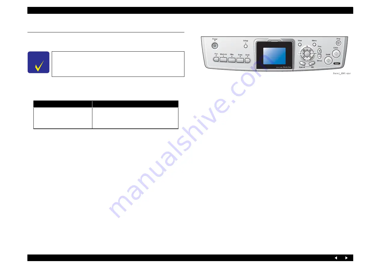
1.3.1  Operation for Forced Power Off

Figure 1-3. Operation Panel

C H E C K

P O I N T

The functions described below, intended for use by service 
personnel, must not be opened to users.

Table 1-12. Operation for Forced Power Off

Switches

Function

Power + Stop
(Press Power SW first, and press 
both switches for more than seven 
seconds)

Turning the power off forcibly (processing 
equivalent to power down)

Содержание Stylus Photo RX700 Series

Страница 1: ...EPSON StylusPhotoRX700 Scanner Printer Copier SERVICE MANUAL ECOS SEMF05001 ...

Страница 2: ...nformed of them The contents of this manual are subject to change without notice The above not withstanding SEIKO EPSON CORPORATION can assume no responsibility for any errors in this manual or the consequences thereof EPSON is a registered trademark of SEIKO EPSON CORPORATION General Notice Other product names used herein are for identification purpose only and may be trademarks or registered tra...

Страница 3: ...E MUST BE CONNECTED USE EXTREME CAUTION IN WORKING ON POWER SUPPLY AND OTHER ELECTRONIC COMPONENTS 4 WHEN DISASSEMBLING OR ASSEMBLING A PRODUCT MAKE SURE TO WEAR GLOVES TO AVOID INJURIES FROM METAL PARTS WITH SHARP EDGES WARNING 1 REPAIRS ON EPSON PRODUCT SHOULD BE PERFORMED ONLY BY AN EPSON CERTIFIED REPAIR TECHNICIAN 2 MAKE CERTAIN THAT THE SOURCE VOLTAGES IS THE SAME AS THE RATED VOLTAGE LISTED...

Страница 4: ...uct APPENDIX Provides the following additional information for reference Connection with Connectors Circuit Boards Component Layout Exploded diagram Parts List Symbols Used in this Manual Various symbols are used throughout this manual either to provide additional information on a specific topic or to warn of possible danger present during a procedure or an action Be aware of all symbols when they...

Страница 5: ...Issue Description A May 9 2005 First Release B June16 2005 Revised the following Ink Cartridges on page 15 Changed the description of print capacity and checkpoint Adjustment Items on page 134 The remained Japanese has been translated ...

Страница 6: ... 2 2 3 3 APG Driving Transmission 24 2 2 3 4 Driving Specifications 25 2 2 4 Paper Feed Mechanism 26 2 2 4 1 PF Motor Specifications 26 2 2 4 2 PF Encoder 26 2 2 4 3 PE Detector 27 2 2 4 4 Transmission Path of Driving Force for Paper Feed 27 2 2 5 CD R Mechanism 28 2 2 5 1 CD R Sensor 1 for Guide 28 2 2 5 2 CD R Sensor 2 for Tray 28 2 2 5 3 CD R Mechanism Explanation 29 2 2 6 Paper Loading Mechani...

Страница 7: ...efore Disassembly 78 4 1 4 Disassembly and Reassembly Procedure 79 4 2 Removal of Exterior Parts 80 4 2 1 Panel Assy 80 4 2 1 1 LCD Assy 81 4 2 1 2 Disassembly of LCD Assy 81 4 2 1 3 Disassembly of Panel Assy 82 4 2 2 Scanner Unit 83 4 2 3 Pressure Pump Assy 85 4 2 4 Main Board Unit 86 4 2 5 Middle Housing 88 4 2 6 Linear Scale 91 4 2 7 Printhead 92 4 2 8 Valve Assy Including Ink Tube Assy 94 4 3 ...

Страница 8: ...ew 140 5 3 2 Starting the Adjustment Program 141 5 4 Scanner Home Position Adjustment 142 5 4 1 Overview 142 5 4 2 Preparations for Use of the Adjustment Program 142 5 4 3 Home Position Adjustment Procedure 143 5 4 4 Home Position Confirmation Procedure 144 5 5 Uploading Firmware 145 5 5 1 Overview 145 5 5 2 Upload Procedure 145 Chapter 6 Maintenance 6 1 Overview 147 6 1 1 Maintenance Error 147 6 ...

Страница 9: ...C H A P T E R 1 PRODUCTDESCRIPTION ...

Страница 10: ...or easy operation USB Host Data in storage devices can be printed Memory card information can be backed up into a storage device Bluetooth or IrDA wireless connection is available as an optional feature 1 1 1 Printer and PC Printing Basic specifications Paper inputs Note Paper thickness 0 1mm Table 1 1 Printer Basic Specifications Items Specifications Print Head Type F Mach Number of nozzles Black...

Страница 11: ...ne 3200 dpi Gray 4 0 ms line 600 dpi 25 6 ms line 3200 dpi Full Color 4 0 ms line 600 dpi 25 6 ms line 3200 dpi Items Specifications Interface USB 2 0 High Speed Command level FS D TBD Scanning resolution 50 6400 dpi selectable in 1 dpi steps 9600dpi 12800dpi Gamma correction User setting 2 levels Special function The following software can be run and scanning operation can be started by operation...

Страница 12: ...n on cool peal Tranfer paper A4 Iron On Iron on cool peal Tranfer paper Letter CD R DVD R Label CD Label 12 cm CD R DVD R Label CD Label 12 cm Table 1 4 Functions Available Copy Function Summary Standard copy General purpose copy mode with 3 mm margins BorderFree copy BorderFree copying suited for making a copy of photo Small margins copy Only EHC Wider printable area provides real copy output Rep...

Страница 13: ...iniSD Adapter required Multi Media Card RS MMC Adapter required Table 1 6 Printing Function Specifications Items Specifications Function Printing image data from another device through the USB Host I F Interface USB 1 1 Support device USB DP PictBrige CD R DVD R drive MO drive Zip drive USB Flash memory Table 1 7 Backup Function Specifications Items Specifications Function Storing image data from ...

Страница 14: ...ing 2 No condensation 3 Under the following conditions Figure 1 1 Environmental Conditions Table 1 10 Primary Power Input Specifications 100 120 V Model 220 240 V Model Rated power supply voltage ACV 100 120 220 240 Input voltage range ACV 90 132 198 240 Rated current A 0 8 A max 1 1 A 0 4 A max 0 55 A Rated frequency Hz 50 60 Input frequency range Hz 49 5 60 5 Power consumption W Approx 25 W Stan...

Страница 15: ...tridge Print capacity in pages Black 600pages A4 360dpi 3 5 duty Color 450pages A4 360dpi 5 duty each color Effective period 6 months after unpacking 2 years in total including 6 months after unpacking Storage temperature Dimensions 42 mm W x 83 mm D x 13 mm H Weight Refilled ink amount 16 4 0 5g Effective ink amount 14 4 g or more 25 duty continuous printing at room temperature Remaining ink amou...

Страница 16: ...specified buttons held down 1 3 1 Operation for Forced Power Off Figure 1 3 Operation Panel C H E C K P O I N T The functions described below intended for use by service personnel must not be opened to users Table 1 12 Operation for Forced Power Off Switches Function Power Stop Press Power SW first and press both switches for more than seven seconds Turning the power off forcibly processing equiva...

Страница 17: ...C H A P T E R 2 OPERATINGPRINCIPLES ...

Страница 18: ...anism p 26 CD R Mechanism p 28 Paper Loading Mechanism p 30 Ink Supply System p 36 Pressure Pump Mechanism p 38 Ink System p 40 In addition to the mechanisms mentioned above the following mechanisms and circuit boards constitute Stylus Photo RX700 Scanner Unit p 41 Main Board p 44 Panel Board p 47 Power Supply Board p 48 Figure 2 1 Schematic Printer Mechanism CR Motor CR Guide Shaft CR Belt Ink Sy...

Страница 19: ...oder 3 3VDC 5 Figure 2 2 2 Ink Cartridge Detector CSIC CSIC 3 Paper Width Detector PW Detector Reflective photo interrupter 3 3VDC 5 Figure 2 2 4 APG Detector 1 Position Transmissive type photo interrupter 3 3VDC 5 Figure 2 3 5 PF Encoder Linear encoder 3 3VDC 5 Figure 2 3 6 PE Detector Transmissive type photo interrupter 3 3VDC 5 Figure 2 3 7 Cover Tray Detector 2 core yellow 3 3VDC 5 Figure 2 2 ...

Страница 20: ...tors and Sensors Printer Housing Figure 2 5 Motors and Sensors Scanner Unit No Name Type Voltage Fig No S1 Scanner CR Motor 4 phase 200 pole HB stepping motor 42VDC 5 Figure 2 5 S2 Scanner Home Detector Transmissive type photo interrupter 3 3VDC 5 Figure 2 5 10 10 12 11 E S1 S2 Carriage Unit Assy ...

Страница 21: ...elector and the driver on the circuit board drive voltage waveform generating circuit Printing method On demand ink jet F Mach head Nozzles Print direction Text Bidirectional shortest distance printing Unidirectional printing Graphics Bidirectional shortest distance printing Unidirectional printing Figure 2 6 Nozzle Arrangement Colors Bk C M Lc Lm Y 6 colors Ink change system None The number of no...

Страница 22: ... Bottom of Carriage Assy Item Specifications Type DC brush motor Mabuchi Motor RS445PB 15205B Voltage 42 V DC voltage 5 voltage applied to the driver Characteristics Armature resistance 23 6Ω 15 Inductance 17 5mH 25 Rotor inertia 20 8 gcm2 Item Specifications Detection method Photo electric conversion system reflection type SHARP GP2S700HCP Electrical characteristics Open collector Collector withs...

Страница 23: ...nd turned OFF during the rest of the period The time resolution of the PWM is 41 7 nsec which is taken as one count The motor is driven in Slow Decay mode and stopped by a short brake Duty 0 Current chopping The slow decay mode chopping OFF time of 50 µsec is always used during current chopping for current control The slow decay mode is such that the blanking time is 6 µsec and both the transistor...

Страница 24: ... Gear 25 6 Spur Gear 20 8 Spur Gear 25 6 On the CR Guide Shaft Front PG Left Cam PG Right Cam PG Right Cam PG Front Left Cam Spur Gear 22 4 Release Assy Carriage Assy Release Assy During CW rotation the Upper Paper Guides are pushed down to set them to the PG state The carriage moves up and down by rotation of the right and left PG Cams Composite Gear 8 22 986 APG Motor Composite Gear 11 22 Compos...

Страница 25: ...ted in sequence posi 1 posi 2 posi 3 posi 4 posi 5 2 The sensor 1 outputs the H and L signals when each PG position area and each area between adjacent positions are detected respectively See the table below for operation modes 3 To set and recognize each PG position area rotate the motor in the posi 5 direction of the sensor 1 until it is stopped by the stopper Then rotate the motor back in the p...

Страница 26: ...per Feed Direction Direction of Motor Rotation Current Normal CW PF A PF B Reverse CCW PF B PF A Item Specifications Detection method SHARP GP1A038CKL Electrical characteristics Supply voltage 3 3 VDC 5 Current 16 mA 40 mA MAX 120Ω Output waveform Phase A and phase B 2 channel digital output TTL Output level H 2 4 V DC min L 0 4 V DC max Resolution 1 180 pulse inch Signal detecting element Photo i...

Страница 27: ...stem transmissive type SHARP GP1S94 Electrical characteristics Open collector Collector withstand voltage 30 V or below Sink current 0 3 mA or below Drive voltage 1 3 3 V 5 Drive voltage 2 3 3 V 5 Detected Condition Switch Mode Detector Output There is no paper Closed 2 4 V or above There is paper Open 0 4 V or below Epicyclic Gear 12 No transmission during CCW rotation PF Roller Assy PF Motor Com...

Страница 28: ... position Detector specifications CD R Tray Signal Before printing in the CDR mode and other times the CD R Guide position is judged CD R Tray not installed CD R Guide error is displayed CD R Tray installed If timer controlled suction and I C replacement are necessary the CD R Tray is ejected and the user is alerted during suction operation If suction operation is unnecessary operation for printin...

Страница 29: ...er and Paper Eject Rollers x2 See Figure 2 15 Figure 2 17 Detection of CD R Guide Position Figure 2 18 CD R Mechanism CD R Sensor 2 CD R Link Lever CD R Guide is retracted CD R Guide is open CD R Right Cam The CD R Link Lever locks the CD R Guide Assy with the CD R Right Cam in the position shown which is detected by the sensor To draw out the CD R Guide push the CD R Guide Assy inward slightly Th...

Страница 30: ...s of Paper Loading Mechanism Item Specifications Type 2 phase 48 pole PM type stepping motor Voltage 42 V DC voltage 5 voltage applied to the driver Characteristics Winding resistance 7 0Ω 10 25 C phase Inductance 10 3mH 20 1kHz 1Vrms 25 C Drive system Bipolar driving 2 2 phase 1 2 phase W1 2 phase 2W1 2 phase 4W1 2 phase constant current driving Driving resolution 1 126 6 inch 0 201 mm pulse 2 2 ...

Страница 31: ... 12 8 x2 Pick Up Clutch Pick Up Retard Shaft Pick Up Belt The belt runs only during CCW rotation of motor Moves the ASF Pick Up Shaft Assy up and down CW Up retracted CCW Down paper transport Composite Gear 17 5 15 2 ASF Gear 17 6 Spur Gear 11 2 Spur Gear 14 4 Transports paper See Flowchart 2 1 p 32 FD Belt ASF Motor Composite Gear 17 5 15 2 ASF Gear 17 6 Spur Gear 11 2 CompositeGear 27 5 15 2 Spu...

Страница 32: ...Rear Trigger Paper Reversing Trigger PaperReversing Clutch Paper Reversing Cam Composite Gear 27 2 15 2 Spur Gear 29 6 PF Rear Clutch LD Roller Assy PF Motor See Flowchart 2 1 p 27 See Flowchart 2 1 p 31 Spur Gear 29 6 Composite Gear 14 7 Trigger Gear 48 Composite Gear 27 5 15 2 Composite Gear PF Roller Assy Idle Roller Shaft Assy Cam Right Hopper By the effect of the cam at the right side of the ...

Страница 33: ... Roller ASF Motor CCW PF Rear Clutch unlocked Does not transmit the driving force to the LD Roller Paper Reversing Clutch unlocked Transmits the driving force from the Idle Roller to the Paper Reversing Shaft FD Belt rotation CCW Lower the ASF Pick Up Shaft Assy The Retard Roller turns to transport paper Paper Reversing Shaft During CW rotation the PF Rear Clutch is locked to transmit the driving ...

Страница 34: ... also supported using the supplied CD R Tray This section outlines the paper paths Figure 2 24 Path of Rear loaded Paper Paper Loading Method Drive Rollers Paper Loading Mechanism PF Mechanism Rear paper loading See Figure 2 24 Retard Roller PF Roller Paper Eject Rollers x2 Front paper loading See Figure 2 25 Pick Up Roller PF Roller Paper Eject Rollers x2 Idle Roller CD R loading See Figure 2 26 ...

Страница 35: ...k Up Roller Paper Eject Rollers The ASF Pick Up Shaft Assy lowers and loads paper PF Roller Paper Eject Rollers When the CD R Tray has been opened manually which is detected by the CD R Sensor 2 the platen gap is set to PG PG is set CD R Sensor 2 CD R Sensor 1 The CD R Sensor 1 detects PG presence absence of the tray and the PW Sensor on the carriage detects the center of the CD ...

Страница 36: ...the Printhead 2 2 8 1 I C Cover Opening Closing Switch Function Detection of I C Cover opening closing appropriate one of the following operations is performed I C Cover is closed Warning is displayed on the LCD or PC monitor I C Cover is open Printing operation is continued Detector specifications Note When the I C Cover Switch has opened signal has turned H during printing Cartridge cover open e...

Страница 37: ...ied to the Printhead the pressure in the Ink Storage Chamber drops so that the Valve Lever is tilted by the Pressure Receiving Plate When the Valve Lever inclines the ink passage from the Ink Tube to the Valve Assy opens so that ink is supplied to the Ink Storage Chamber When the Ink Storage Chamber is filled with ink the Valve Lever tilted by the Pressure Receiving Plate is raised so that the Val...

Страница 38: ...th both the transistors on the sink side turned ON synchronous rectification is enabled in the active mode Unless specified the motor is stopped by a short brake duty 0 Current chopping method The slow decay mode chopping OFF time of 50 µsec is always used during current chopping for current control The slow decay mode is such that the blanking time is 6 µsec and both the transistors on the sink s...

Страница 39: ...sors are H the motor is stopped by a short brake Duty 0 via stop control Initial pressurization raises the pressure up to above the threshold value of the Pressure Sensor to reduce the required number of pumping actions If Cover OPEN is detected during the driving of the Pressure Motor the motor is stopped by a short brake Duty 0 immediately without via the stop control Pressure Pump reset Release...

Страница 40: ... driving resolution motor 1 067 degrees pulse 2 2 phase conversion Drive Mode Suction Speed Name Revolving Speed of Pump Wheel revolutions s Suction Flow Rate g s IS7 Constant value drive 2 IS6 Constant value drive IS5 Low speed 0 8 TBD IS4 Normal 2 2 TBD IS3 High speed 3 TBD IS2 Super high speed 1 5 TBD IS1 Super high speed 2 6 TBD Direction of Pump Motor Rotation Operation of Pump Unit Countercl...

Страница 41: ...ain Board to the CR Motor CR Motor Unit Moves the CCD Unit right and left via the Timing Belt TPU Assy Works as the light source for scanning negative or positive film incorporating an inverter board and a lamp Users can remove the TPU Assy by disconnecting the Film Scan Connector from the Exterior Assembly Figure 2 32 Components of Scanner Unit Figure 2 33 Transmission Path of Driving Force from ...

Страница 42: ...5D1010 Voltage 42 V 5 Basic characteristics Winding resistance 6 3Ω 10 25 C phase Inductance 5 6mH 20 1kHzÅA1VrmsÅA25 C Step angle 1 8 Full step Drive system Bipolar constant current driving Maximum rating Power supply voltage 50 V output current 800mA per phase Item Specifications Detection method Light transmission type BRIGHT LED ELECTRONICS BPI 3CI 05 ScanArea01 eps Guaranteed scanning area fo...

Страница 43: ...er ICs RENESAS M63160J are mounted each of which controls two DC motors and one stepping motor The band width is ensured by setting the operating frequency of the local SDRAM of SOC at 96 MHz High speed processing is ensured because all the processing from scanning to binarization Microweave and image buffer generation is carried out inside the SOC without via the CPU bus Equipped with a color LCD...

Страница 44: ...ircuit ASIC Card power supply control circuit Scanner section Scanner interface circuit Motor control and drive circuit Scanner Scanner HP detection interface circuit TPU interface circuit 2 3 3 2 Environmental Conditions Operating temperature 0 70 C inside the case Operating humidity 30 70 RH inside the case no condensation 2 3 3 3 Power Supply Specifications Supply voltage for main power system ...

Страница 45: ...G or the equivalent 128 Mbits Application Work memory for copy function Bus width 16 bits Power supply 3 3 V single power supply Capacity 256 Mbit 4 M x 16 bits x 4 banks 256 Mbits 128 Mbit 2 M x 16 bits x 4 banks 128 Mbits Package 54 pin TSOP Operating frequency 133 MHz CL 2 or higher RTC circuit IC3 RTC9824 by Seiko Epson Composite IC for reset function RTC and EEPROM CR PF Pump motor drive circ...

Страница 46: ...1 5 V 0 8 A Max 1 2 A Oscillation circuit Model Q22FA23800046 Element Crystal oscillator Frequency 48 000 MHz 500 ppm or less Remarks 45 55 Duty IC Location Functions IC Location Functions ASIC for card section control IC10 Name E09A56B by NEC Manufacturing process 0 35Éþ cell base IC CB9 VX Package 144 pin QFP Supply voltage 3 3 V single power supply Operating frequency 64 MHz bus clock and 48 MH...

Страница 47: ...face illuminant Recognition method Presence or absence of connections of SOC port input and SOC port output Grounding of the power supply is detected by SOC port input Regulator Name PQ12DZ5UJ00H Sharp Application Circuit to generate the 12 V power for scanner Input voltage 12 5 V 14 V Capacity 0 15 A Switch Functions Functional switches Operation power switch Type Embossed sheet Circuit Connected...

Страница 48: ...I O CN2 5 V generation circuit 42 V input 3 3 V 0 8 A 1 5 V 0 8 A 15 V input 12 V 0 15 A 3 3 V generation circuit 1 5 V generation circuit 12 V generation circuit Item 100 120 V Specifications 220 240 V Specifications Power Supply Unit C583 PSB C583 PSE Rated input voltage 100 120VAC 220 240VAC Input voltage range 85 138VAC 187 276VAC Rated input power frequency 50 60Hz Input frequency range 47 63...

Страница 49: ...put voltage 42V 15V 5V Output voltage range 1 40 44V 13 21V 4 4 75 5 25V Rated output current 0 8A 0 15A 1 2A Output current at starting stop or in low power mode 0 24A or below 0 15A or below 0 6A or below Output current range 0 2 0A 3 0 0 15A 0 1 2A Ripple voltage 2 100mVpp Typ 100mVppTyp 100mVpp Typ Spike voltage 2 500mVpp Typ 300mVpp Typ 300mVpp Typ Item Outputs of the C583 MAIN Board Output 4...

Страница 50: ...ing temperature range 0 50 C Storage temperature range 30 70 C Life input and output conditions rated input and output 10000 hours or more Ambient temperature 50 C Dimensions 51 6 x 210 x 31 6 mm Reference for height Component side of circuit board Signal Name PS Control Signal PSC Functions At power ON The Power Supply Unit becomes active immediately when the PSC terminal is opened At power OFF T...

Страница 51: ...C H A P T E R 3 TROUBLESHOOTING ...

Страница 52: ... voltage at the wall outlet The POWER CORD must be free from damage short circuit or breakage or miswiring in the POWER CORD The printer must be grounded properly The printer should not be located in a place where it can be exposed to too high or low temperature too high or low humidity or abrupt temperature change The printer should not be located near waterworks near humidifiers near heaters or ...

Страница 53: ... 1 Procedure for Troubleshooting To Troubleshooting for Individual Units No Yes Problem solved Perform Preliminary Checks p 52 Does the error recur No Yes Is there any error display Yes No By referring to Error List p 54 identify the error and repair it Also refer to Troubleshooting in Basic Operation Guide Troubleshooting for Printer p 65 Ink Supply Related Troubleshooting p 70 I F Related Troubl...

Страница 54: ... When the ink cover is open Replace the following ink cartridge and close the ink cover Left Right Black T5591 Magenta T5593 Cyan T5592 Light Magenta T5596 Light Cyan T5595 Yellow T5594 Ink has been replaced correctly Ink related message 7 An unrecognizable ink cartridge has been detected Ink cartridges cannot be recognized Replace the following ink cartridge Left Right Black T5591 Magenta T5593 C...

Страница 55: ...and press the Color button Press the Color button to feed paper correctly Jam error Paper has jammed Paper jam Press the Color button If the error is not cleared please clear by hand Remove paper Maintenance error The printer requires maintenance due to waste liquid overflow or elastomer tube replacement time etc Service required Parts inside your printer are at the end of their service life See y...

Страница 56: ...heet and card The contents of the memory card have changed Print a new Index Form and try again Displayed for a specified time approx 5 seconds CDR DVD guide open at startup initialization Displayed when the guide was open when printing started at startup initialization The guide for CD DVD print is opened Close the guide The guide has been stored Name card long edge first insertion error A name c...

Страница 57: ...kground color basic character size or the like cannot be specified as intended at the send side Error in the data stream the document cannot be printed very well Press any key A part of the reference object cannot be buffered BT MIME While XHTML Print data could be decoded a part of all of reference object decoding was abandoned due to memory shortage or excess of the max number of objects to be h...

Страница 58: ...593 Cyan T5592 Light Magenta T5596 Light Cyan T5595 Yellow T5594 This ink cartridge is not genuine Do you use this ink cartridge Yes Ok Button No Back Button Press the OK button or Back button Ink related message 4 A Non brand ink was installed Open the ink cover and set the ink cartridge Left Right Black T5591 Magenta T5593 Cyan T5592 Light Magenta T5596 Light Cyan T5595 Yellow T5594 Ink cartridg...

Страница 59: ... or breakage Checking the lead wires of the CR Motor Relay Connector CN19 for disconnection or breakage Checking the CR Encoder FFC CN3 for disconnection or breakage Checking the CR Guide Shafts Main Sub for adhesion of dirt or insufficient lubrication Checking the Linear Scale for adhesion of dirt or damage p 91 Checking the CR Encoder for adhesion of dirt or damage p 118 Checking the PW Sensor f...

Страница 60: ...ply Board p 109 FEH PF speed over error FAH Measurement value error in PF Duty limiting control EFH Position error in PF BS control F0H DTY_max error in PF BS control FDH PF position protection FCH Speed over error in PF BS control F2H PF PID drive time out judgment error F3H PF BS drive time out judgment error APG motor 70H APG error normal drive error An error occurred in the APG operating seque...

Страница 61: ...he connection of the connectors and routing of the lead wires Checking the motor in question and the following parts and replacing the defective part Main Board p 86 Power Supply Board p 109 D2H CR load positioning drive time out D3H PF PID drive time out D4H PF BS drive time out D5H ASF drive time out D6H Pump drive time out D7H APG drive time out D8H Pressure Pump drive time out Factory command ...

Страница 62: ...118 Checking the CR Motor and replacing it if necessary p 115 Main Board p 86 Power Supply Board p 109 51H CR unlocking error 52H CR locking error Sensor error 60H PW detection error Hi check error PW detector trouble Checking the PW Sensor p 118 Checking the PW Sensor for adhesion of dirt and dust Checking the connection of the FFC PW Sensor CR Encoder Board Main Board Making the following adjust...

Страница 63: ...EPSON Stylus Photo RX700 Revision A Troubleshooting Overview 63 Flowchart 3 1 Printer Power ON Flags that are not stored in memory at power OFF Paper set flag CR locking flag PF drive blocking flag ...

Страница 64: ...EPSON Stylus Photo RX700 Revision A Troubleshooting Overview 64 Flowchart 3 2 Printing Processing ...

Страница 65: ... paper feed operation several times to clean the surface of the LD Roller or Retard Roller If these steps do not correct the problem replace both the LD Roller and Retard Roller Pick Up Roller and Idle Roller dirty or worn Check to see if no Micro Pearl or oily substance is adhering to the rollers Wipe the rollers with a cloth dampened with alcohol Operation of paper loading mechanism is abnormal ...

Страница 66: ...number of printed sheets using the adjustment program Initialize the PF degradation compensation counter and write the maximum value Faulty operation of Paper Eject Roller Check to see if Paper Eject Roller rotates correctly Properly engage the gears driving the Paper Eject Roller Table 3 6 Diagnostics when carriage action is abnormal Condition Cause Check Point Remedy Abnormal carriage operation ...

Страница 67: ... Encoder not operating properly Check to see if Encoder FFC is connected to CR Encoder Board Connect the Encoder FFC to the CR Encoder Board Check for paper bits and dust adhering to CR Encoder Remove paper bits and dust adhering to the CR Encoder Check for damaged Encoder FFC Replace the Encoder FFC Check for damaged CR Encoder Replace the Carriage Unit Rotary Scale not operating properly Check t...

Страница 68: ...roblem with the Head FFC to Printhead connection replace the Printhead Vertical lines are not in alignment Bi D adjustment is not made Check to see if Bi D adjustment has been done properly Perform Bi D adjustment White lines appear in output data Dirt is adhering to CR Guide Shaft Check for dirt adhering to surface of CR Guide Shaft Clean the surface of the CR Guide Shaft with a soft dry cloth PF...

Страница 69: ...he normal power cord Replace the power cord Abnormal AC power voltage Check the AC power voltage Supply the normal power Faulty connection of the connector Check the connection between the Power Supply Board Main Board CN28 Correct the connection Fuse blown Check the fuse F1 on the Power Supply Board Replace the fuse with a new one Abnormal output voltage of Power Supply Board Check the output vol...

Страница 70: ...nting is erratic Condition Cause Check Point Remedy Carriage moves correctly but printing is not normal Ink Cartridge not operating properly Install a new ink cartridge and test printing Replace the ink cartridge FFC not connected properly Check the FFC connection between each CSIC Board Main Board Connect the FFC firmly Cleaner Blade not operating properly Check for debris adhering to Cleaner Bla...

Страница 71: ...ap to Ink Tube Pump tube collapsed Visually check tube Replace the Ink System Assy Cap is dirty or damaged Check for foreign object adhering to Cap or damaged Cap Remove foreign object in Cap with cotton swab If Cap is damaged replace the Ink System Assy Tube is disconnected from Cap bottom Visually check for disconnection of tube from Cap lower bottom Connect the tube properly Cap does not slide ...

Страница 72: ...d Check to see if main board is not damaged Replace the main board Table 3 14 Troubleshooting for Memory Card Cause Check Point Remedy Driver has not been installed correctly Check to see if a memory card is recognized in the single unit mode Temporarily remove the driver and then install it again Data has been destroyed Data on card may be destroyed owing to static electricity Check to see if car...

Страница 73: ...is received error status is cancelled Turn the power off once and then turn it on again Scanner open Scanner cover is open Close the cover Table 3 16 Observation of Trouble and Reference for Remedy Observation Description of Trouble Reference for Remedy Even with power turned on the machine does not operate The machine does not operate for initialization Table 3 17 Fatal error occurred Indication ...

Страница 74: ...rd Table 3 19 Carriage operates but error indicated Cause Check Point Yes No Remedy Upper case of scanner is removed Upper case of scanner is removed Yes Install the upper case Defective main board Replace the main board Defective CR HP sensor Replace the CR HP sensor board Table 3 20 Fluorescent lamp does not turn on Cause Check Point Yes No Remedy Connector CN20 on main board is disconnected Con...

Страница 75: ...ure Pump Assy CN18 Pin 1 2 64 7Ω 15 ASF motor Relay Connector White Pin 1 3 Pin 2 4 7 0Ω 10 APG motor Relay Connector Black Pin 1 2 64 7Ω 15 CR motor Scanner Unit Pin 1 2 Table 3 23 Sensor Check Sensor Name Location Signal Level Sensor Status Pressure Pump HP Sensor CN16 Pin x x H Cover Open L Cover Closed PE sensor CN30 Pin x x On 2 4V or over On Paper absent Off less than 0 4V Off Paper present ...

Страница 76: ...C H A P T E R 4 DISASSEMBLYANDASSEMBLY ...

Страница 77: ...precautions described in the next section before starting W A R N I N G Remove the batteries and plug off the AC adapter before disassembling the Stylus Photo RX700 Always wear gloves for disassembly and reassembly to avoid injury from sharp metal edges Lithium batteries are installed on the main board of this product Never fail to observe the following instructions when serving the batteries 1 Ke...

Страница 78: ...btained replace also the relevant service parts with new ones C A U T I O N Use only recommended tools for disassembling assembling or adjusting the Stylus Photo RX700 Observe the specified torque when tightening screws Make the specified adjustments when you disassemble the Stylus Photo RX700 See Chapter 5 for details Use the special package for transportation Prior to disassembly and reassembly ...

Страница 79: ...ssembly of LCD Assy p 81 C H E C K P O I N T Stylus Photo RX700 does not have any mechanism that permits the operator to unlock the carriage Therefore turn the power ON and turn it OFF timely after seeing the movement of the carriage to locate it at a position other than the home position As soon as the repaired product has been returned to the user there may be a case a maintenance call occurs be...

Страница 80: ...from the printer 6 Disconnect the FFCs of the LCD and Panel Board from the Main Board Figure 4 1 Removing the Panel Assy C A U T I O N Take care not to damage any cables with any screw that is projecting from the Shield of the Main Board Before installing the Middle Cover make sure that the cables are routed properly without any of them placed over the post on the bottom of the Middle Cover Instal...

Страница 81: ...g the LCD Assy Figure 4 3 Disassembling the LCD Assy C A U T I O N Take care not to bend the Panel Ground Plate on the back side when performing disassembly and assembly with the Panel Ground Plate installed C A U T I O N Take care that the surface of the removed LCD is kept free from scratches or dust and dirt Install the LCD Module so that it is exactly horizontal and route the lead wires proper...

Страница 82: ...l Assy C A U T I O N Take care not to scratch the surface of the LCD Panel when performing disassembly and assembly with the LCD Assy installed Make sure that the Panel Board are engaged with the hooks three of the panel housing When installing the Panel Ground Plate make sure that its projection is fitted into the hole in the Panel Shield Plate Panel Ground Plate Panel Ground Plate Hooks three To...

Страница 83: ... from the printer frame Continued to next page Figure 4 5 Removing the Scanner Unit C A U T I O N When removing the Scanner Unit take care not to break the ground cable which is connected to the printer With the FFC disconnected take care not to break the ferrite cores by hitting them against each other C H E C K P O I N T Remove the Scanner Unit while holding it in an open position from the print...

Страница 84: ...nit as shown at right in the Middle Housing so that the Scanner Unit can be opened smoothly without folding the FFCs Install the ferrite cores x2 and the FFC Clamp at the locations shown below A D J U S T M E N T R E Q U I R E D Refer to the following section and perform the necessary adjustments 5 1 1 Adjustment Items p 134 FFC Clamp Ferrite Core Tape Ferrite Core ...

Страница 85: ...ows cannot be damaged during the removal or installation of the screws Take care not to damage the tube of the Pressure Pump Assy and take care that the connected end does not whiten or is not bent When connecting the tube make sure that it is all the way seated Before installing the Pressure Pump Assy place the power cable properly by forming it into a loop See the figure at right After installin...

Страница 86: ...ain Board is to be replaced refer to the following section and back up the data in EEPROM before starting disassembly if possible 5 1 1 Adjustment Items p 134 Screw Qty Tightening Torque C B P Tite 3x6 F ZN 3C 3 0 8 0 1 N m C B S Tite 3x10 F ZN 3C 5 0 6 0 1 N m C H E C K P O I N T The removal procedure for the Main Board Unit is completed here You can start the procedure for removing any other sub...

Страница 87: ...eplaced with a new one refer to the following section and perform the necessary adjustments 5 1 1 Adjustment Items p 134 Table 4 2 Main Board Connector List CN No Color Pins Connected to 3 FFC 8 CR PW Sensor 4 FFC 5 PF Encoder 5 White 2 I C SW 1 Right 6 FFC 17 Printhead Lower 7 FFC 17 8 FFC 17 Printhead Upper 9 FFC 17 10 Red 2 I C SW 2 Left 11 FFC 23 CSIC 1 Right 12 FFC 23 CSIC 2 Left 13 Yellow 2 ...

Страница 88: ...lead wires and FFCs Continued to next page Figure 4 13 Removing the Middle Housing C A U T I O N When removing or installing the Middle Housing take care not to tilt the printer more than 90 degrees Otherwise ink leakage may occur inside the printer Release the right and left hooks at the bottom of the Front Cover as shown at right so as to avoid damaging them Screw Qty Tightening Torque C B P Tit...

Страница 89: ... for properness Connection of each Waste Ink Tube x2 See Figure 4 14 Connector orientation and routing of TPU Harness See Figure 4 15 Clearance around each post on the rear of the Middle Housing x2 See Figure 4 17 Placing of Relay Connectors See Figure 4 16 Use of Harness Clamp and fastening of lead wires See Figure 4 16 Installation of Linear Scale Waste Ink Tube Blue Waste Ink Tube Red Confirm t...

Страница 90: ...tor Yellow Tray Cover Sensor Connector Red Tray Cover Sensor Connector FFCx4 Head FFC FFC CR Encoder Board Black CD R Sensor 1 Connector FFC Left I C Holder White Relay Connector Yellow PE Sensor Assy Connector Blue CD R Sensor 2 Connector White APG Sensor Connector White TPU Harness Connector FFC PF Encoder Install the ferrite core for the CR Encoder FFC CN3 Route the lead wires of the following ...

Страница 91: ...g the Linear Scale C A U T I O N When you hold the Linear Scale hold its ends or two points of the top and bottom surfaces with your hands do not touch the reading surface Take care that the reading surface is not soiled or scratched C H E C K P O I N T Stylus Photo RX700 does not have any mechanism that permits the operator to unlock the carriage Therefore turn the power ON and turn it OFF timely...

Страница 92: ... the FFCs x2 Continued to next page Figure 4 20 Removing the Printhead C A U T I O N Take due care not to stain any surrounding objects with ink The ink tubes are very delicate Take due care not to bend or whiten them by applying undue force C H E C K P O I N T Stylus Photo RX700 does not have any mechanism that permits the operator to unlock the carriage Therefore turn the power ON and unplug the...

Страница 93: ...be Guide and connect them to the Valve Assy In doing so to facilitate your work you are advised to place a sheet of paper bent into a shape of mountain over the FFCs and remove it after installing the Valve Assy See Figure 4 22 A D J U S T M E N T R E Q U I R E D Adjustments are required When the Printhead has been replaced with a new one refer to the following section and perform the necessary ad...

Страница 94: ... Guide Ground Plate Continued to next page Figure 4 23 Disconnecting the Tubes Figure 4 24 Removing the Valve Assy C A U T I O N Take due care not to stain any surrounding objects with ink The ink tubes are very delicate Take due care not to bend or whiten them by applying undue force C A U T I O N The Joint Clamp Spacer Ink Joints Black x3 and Pressure Tube White are likely to be damaged once the...

Страница 95: ...prevent the ink tubes from being elongated or contracted excessively Figure 4 25 Connecting the Ink Tubes Figure 4 26 Installing the Tube Guide Ground Plate Figure 4 27 Installing the Tube Stopper C A U T I O N In this process there is a possibility of ink leakage Take great care not to stain any surrounding objects with ink The ink tubes are very delicate Take due care not to bend or whiten them ...

Страница 96: ...and assembly on a clean bench is ideal Perform disassembly and assembly with care not to damage the document table glass In addition never forget that a very troublesome cleaning is required if dirt sticks to the inside of the document table A D J U S T M E N T R E Q U I R E D When the Scanner Housing is removed make the following adjustment after reinstallation 5 4 Scanner Home Position Adjustmen...

Страница 97: ...e Scanner Unit in an environment that minimizes intrusion of dust and dirt Disassembly and assembly on a clean bench is ideal There is a possibility of damaging the right and left shanks of the ASF Cover when removing the Scanner Housing To prevent such damage remove the ASF Cover beforehand Perform disassembly and assembly with care not to damage the document table glass In addition never forget ...

Страница 98: ... Figure 4 30 3 Lift the right side of the Carriage Cover and remove it from the carriage release the lead wires from the hooks x2 and disconnect the connector Figure 4 29 Removing the HP Board Figure 4 30 Removing the Carriage Cover Assy After connecting the connector route the lead wires as shown below When installing the Carriage Cover fit the projections x2 at the left edge first Of the two scr...

Страница 99: ...d remove the Timing Belt together with the Drive Pulley Figure 4 31 Removing the CR Motor Unit C H E C K P O I N T See below for disassembly of the CR Motor Unit Lubrication is necessary Refer to the following section and lubricate the specified points Lubrication of CR Motor Unit p 162 Tighten the screws in numerical order shown at right Nut x3 Torque 0 54 0 5N m M3x5 Ni Torque 0 88 0 1N m Tighte...

Страница 100: ...p and the Timing Belt Figure 4 32 Removing the CCD Unit Figure 4 33 Sticking the Double stick Tapes Fix the HP Sensor FFC with double stick tape x3 and fix the FFC Ground Plate with double stick tape that must be stuck in the area shown at right beforehand See Figure 4 33 Fix the CCD Unit FFC with the double stick tape that must be stuck on the FFC Ground Plate Route the ground cable as shown at r...

Страница 101: ...t the connectors x2 of the TPU Board remove the screws x2 and remove the TPU Board together with the cover Figure 4 34 Disassembling the TPU Assy Route the lead wires of the TPU Lamp as shown below To secure the Reflector Assy tighten the screws in numerical order shown at right When installing the TPU Housing Upper tighten the screws in numerical order shown below Torque 0 44 0 1N m 3x8 Ni x7 TPU...

Страница 102: ...er Assy p 105 Printer Mechanism p 107 Removal of Exterior Parts p 80 APG Assy p 111 Valve Assy Including Ink Tube Assy p 94 Waste Ink Pads Lower Case p 110 CR Motor p 115 PE Sensor Assy p 122 Carriage Assy p 116 Rear Paper Guide Assy p 114 Power Supply Board p 109 PF Motor p 125 Release Assy p 121 Upper Paper Guides p 123 Idle Roller Shaft Assy p 124 PF Roller Assy PF Encoder Assy p 126 Waste Ink ...

Страница 103: ...and remove the Nylon Clip 6 Disconnect all the cables from the ASF Rear Assy 7 Remove the right and left screws x2 8 Disengage the hooks x2 on the CR Motor side and the hooks x2 on the front side and remove the ASF Rear Assy Continued to next page Figure 4 35 Removing the ASF Rear Assy LD Roller Guide Torque 0 8 0 1N m C B S Tite 3x6 F ZN 3C Spacer ASF Rear Assy Hooks x2 Torque 0 6 0 1N m C B S Ti...

Страница 104: ...the APG Assy connect the connectors x4 and secure the Nylon Clip with the screw NOTE Install the Nylon Clip with its flat surface facing outward 8 Pass the lead wires of the PE Sensor Assy yellow CD R Sensor 2 blue and APG Sensor white through the Harness Clamp Figure 4 36 Routing and Fastening of Lead Wires Lubrication is necessary Refer to the following section and lubricate the specified points...

Страница 105: ...t I C Holder Assy by shifting it to the left while disengaging it from the locating boss on the left side first and then by sliding it toward the front 11 Remove the I C Holder Assy from the printer Figure 4 37 Removing the I C Holder Assy C A U T I O N In this process there is a possibility of ink leakage Take great care not to stain any surrounding objects with ink Take care during work not to d...

Страница 106: ...Holder Assy p 105 3 Remove the right and left Waste Ink Pads Figure 4 38 Waste Ink Pads C A U T I O N Take due care not to stain any surrounding objects with waste ink A D J U S T M E N T R E Q U I R E D On the occasion of replacing the Waste Ink Pads with new ones as required by a maintenance error replace all the specified parts with new ones and clear the counter value 6 1 1 Maintenance Error p...

Страница 107: ...Waste Ink Tubes x2 from the Tube Holder 8 Remove the Printer Mechanism with care that it is not caught by lead wires Continued to next page Figure 4 39 Removing the Printer Mechanism C A U T I O N When you remove the Waste Ink Tubes ink may blow out Take great care not to stain any surrounding objects with ink When installing the Waste Ink Tubes make sure that they are all the way seated in the lo...

Страница 108: ...at the Waste Ink Tubes x2 are connected to the Tube Holder properly See p 107 A D J U S T M E N T R E Q U I R E D Adjustments are required Once the Printer Mechanism has been removed or replaced with a new one refer to the following section and perform the necessary adjustments 5 1 1 Adjustment Items p 134 Harness Clamp temporally fixed Relay Connector Routing of the Power Supply Board harness TPU...

Страница 109: ...the ground screw 6 Remove the screws x5 securing the Power Supply Board and remove it from the Lower P S Shield Plate Figure 4 43 Removing the Power Supply Board A D J U S T M E N T R E Q U I R E D Adjustments are required When the Power Supply Board has been replaced with a new one refer to the following section and perform the necessary adjustments 5 1 1 Adjustment Items p 134 電源ユニット TPU Connect...

Страница 110: ...care not to stain any surrounding objects with waste ink Before installing the Waste Ink Pads make certain that the Waste Ink Tubes have been install in the proper locations respectively A D J U S T M E N T R E Q U I R E D On the occasion of replacing the Waste Ink Pads with new ones as required by a maintenance error replace all the specified parts with new ones and clear the counter value 6 1 1 ...

Страница 111: ...kwise fully and insert a pin into the APG Assy Holder to align the hole in the APG Assy Holder with that in the composite gear See Figure 4 46 3 Fit the projections x2 of the APG Assy into the printer frame adjust the positions of the mark on the gear of the CR Guide Shaft and the mark on the gear of the APG Assy as shown below and tighten the screws PG Cam The locating hole in the PG Cam and the ...

Страница 112: ... T I O N The print quality may be degraded if skin grease adheres to the wiper Do not touch the wiper with your bare hand C H E C K P O I N T For easy work you are advised to move the carriage from the home position before disassembling the Stylus Photo RX700 Move the carriage by turning power ON and then turning it OFF timely Before tightening the screw check that the projections x3 are located a...

Страница 113: ... p 112 3 Remove the screws x2 at the right side of the printer and remove the ASF Motor 4 Remove the screws x3 and remove the Paper Path Switching Assy Figure 4 49 Removing the Paper Path Switching Assy Locate the ASF Drive Assy ASF Motor Paper Path Switching Assy as shown below ASF Motor Paper Path Switching Assy Torque 0 8 0 1N m C B S Tite 3x6 F ZN 3C x3 Torque 0 6 0 1N m C B P Tite 3x8 F ZN 3C...

Страница 114: ...e screw on the Projection side and remove the Paper Guide Bank Separation from the Paper Feed Lower Cover Figure 4 50 Removing the Rear Paper Guide Assy Figure 4 51 Paper Guide Bank Separation Lubrication is necessary Refer to the following section and lubricate the specified points Lubrication of Driven Pulley Assy p 154 Install the Paper Guide Bank Separation so that the projection of the Paper ...

Страница 115: ...e the CR Motor from the printer frame Figure 4 52 Removing the CR Motor Lubrication is necessary Refer to the following section and lubricate the specified points Lubrication of Driven Pulley Assy p 154 A D J U S T M E N T R E Q U I R E D Once the CR Motor has been replaced with a new one refer to the following section and perform the necessary adjustments 5 1 1 Adjustment Items p 134 Driven Pulle...

Страница 116: ...e CR Scale Spring 8 Remove the retaining rings x2 from the CR Guide Shafts and remove the PG Cams x2 coned disc springs x2 and washers x2 9 Remove the CR Scale Mounting Plate Assy and washers x2 and lift the right side of the CR Guide Shafts x2 and remove the Carriage Assy from the left frame 10 Pull out the CR Guide Shafts x2 from the Carriage Assy Continued to next page Figure 4 53 Removing the ...

Страница 117: ...l the central gear and fix it in place with the retaining ring 11 Set the retaining rings x2 on both CR Guide Shafts and install the CR Scale Spring Figure 4 54 Installing the Carriage Assy Figure 4 55 Positioning of CR Guide Shafts Lubrication is necessary Refer to the following section and lubricate the specified points Lubrication of Driven Pulley Assy p 154 Lubrication of Carriage Assy p 156 S...

Страница 118: ...gure 4 57 3 Disconnect the FFC PW Sensor from the Encoder Board 4 Remove the screws x2 and remove the Encoder Board 5 Remove the screw and remove the PW Sensor Cap 6 Remove the PW Sensor from the Carriage Assy Figure 4 56 Removing the Timing Belt Figure 4 57 Disassembling the Carriage Assy Install the CR Timing Belt to the Timing Belt Holder in such a way that the portion provided with teeth on bo...

Страница 119: ...ing the Paper Guide Front Assy bend the waste ink guides x2 of the Paper Guide Front Assy inward so that the waste ink will flow into the Waste Ink Pads under the Printer Mechanism Lubrication is necessary Refer to the following section and lubricate the specified points Lubrication of Paper Guide Front Assy p 152 When installing the Paper Guide Front Assy put the right side shaft holder portion u...

Страница 120: ...e Lower Paper Guide with care not to stain any surrounding objects with ink Figure 4 59 Removing the Waste Ink Pads Platen Area C A U T I O N Take due care not to stain any surrounding objects with waste ink Place the waste ink pads under the hooks of the Lower Paper Guide A D J U S T M E N T R E Q U I R E D On the occasion of replacing the Waste Ink Pads with new ones as required by a maintenance...

Страница 121: ...move the CD R Sensor 2 as follows remove the screw x1 remove the CD R Sensor Cover and then remove the CD R Sensor 2 Lubrication is necessary Refer to the following section and lubricate the specified points Lubrication of Release Assy p 153 Install the Release Assy as follows engage all the hooks with the frame properly and tighten the screws while pressing the Release Assy from above so that the...

Страница 122: ...E Sensor Assy 1 Remove the Printer Mechanism p 107 2 Disengage the hook and slide the PE Sensor Assy upward and remove it Figure 4 62 Removing the PE Sensor Assy After installing the PE Sensor Assy route the lead wires as shown below Rear Front Disengage the hook from the direction of front and slide it upward PE Sensor Assy ...

Страница 123: ...m the direction of the rear of the printer release the springs x4 of the Upper Paper Guides from the hooks of the printer frame and remove them from the Upper Paper Guides 5 Lift each of the Upper Paper Guides slightly and remove it from the printer frame Figure 4 63 Removing the Upper Paper Guides Removing the spring Upper Paper Guides x4 Rear Springs x4 Rear Upper Paper Guides Rear Frame Lift th...

Страница 124: ...ion of the Bush on the PF side of the Idle Roller Shaft Assy and remove the Bush by turning it 10 Slide the Idle Roller Shaft Assy to the PF side and remove it from the printer frame Figure 4 64 Removing the Idle Roller Shaft Assy C A U T I O N Do not touch any of the rubber rollers of the Idle Roller Shaft Assy with your bare hand The rubber rollers must be free from dust and dirt Otherwise the p...

Страница 125: ...procedure 1 Tighten the upper screw loosely 2 Secure the PF Motor temporarily while pulling the PF Motor obliquely downward to take up the PF Timing Belt 3 Make the belt tension adjustment specified below for the PF Motor and tighten up the screws A D J U S T M E N T R E Q U I R E D Once the PF Motor has been removed or replaced with a new one refer to the following section and perform the necessa...

Страница 126: ...re 4 66 Removing the PF Roller Assy PF Encoder Assy Figure 4 67 Removing the PF Roller Holder Support Assy C A U T I O N Take care during work not to scratch or soil the encoder scale area of the PF Roller Assy Do not touch the coated surface of the PF Roller Shaft with your bare hand and do not scratch it Otherwise the paper feed quality may be degraded Lubrication is necessary Refer to the follo...

Страница 127: ...from the CD R Shaft and remove the CD R Gear 17 6 and parallel pin 8 At the bottom remove the E type retaining ring from the CD R Shaft detach the parallel pin and pull out the CD R Shaft from the CD R Guide Assy 9 Remove the CD R Guide Assy from the printer frame while pressing the right and left shanks of the CD R Guide Assy inward Continued to next page Figure 4 68 Removing the CD R Guide Assy ...

Страница 128: ... type retaining ring to the CD R Shaft 6 At the right side install the parallel pin CD R Gear 17 6 and E type retaining ring on the CD R Shaft 7 Install the CD R Right Cam and install the washer and E type retaining ring 8 Attach the CD R Link Lever set the spring and Spring Cover in place and install the CD R Stopper 9 Install the CD R torsion springs at both sides Continued to next page Figure 4...

Страница 129: ...ly The tips of the latches must press on the EJ Frame Assy The right and left block levers are laid rearward See Figure 4 77 Figure 4 71 Checking the Springs of the CD R Guide Assy Figure 4 72 Checking the Link Area of the CD R Guide Assy Figure 4 73 Checking the Link Lever of the CD R Guide Assy Figure 4 74 Checking the Horizontality of the CD R Shaft C H E C K P O I N T If the CD R Guide Assy do...

Страница 130: ...e Guide 8 At the right side remove the screws x2 and remove the Right Rack and Right EJ Link 9 Release the shank of the EJ Frame Assy from the groove in the Left Rack and remove the EJ Frame Assy Continued to next page Figure 4 75 Removing the EJ Frame Assy C A U T I O N When installing or removing the EJ frame torsion springs take care not to bend the spring catches of the printer frame Right EJ ...

Страница 131: ...ecking of EJ Frame Assy After assembling the EJ Frame Assy check the following conditions for properness See Figure 4 77 When the EJ Frame Assy is moved back and forth the Right and Left EJ Links move together The right and left block levers have been turned over to the front Figure 4 76 Installing the EJ Frame Assy Figure 4 77 Checking the EJ Frame Assy C A U T I O N When installing the EJ frame ...

Страница 132: ...on spring at the bottom of the printer 4 Remove the two screws for the ASF Pick Up Shaft Assy 5 Slide the ASF Pick Up Shaft Assy and remove it together with the Gear 14 4 Figure 4 78 Removing the ASF Pick Up Shaft Assy Lubrication is necessary Refer to the following section and lubricate the specified points Lubrication of ASF Pick Up Shaft Assy p 161 Torque 0 8 0 1N m C B S Tite 3x6 F ZN 3C x2 Pi...

Страница 133: ...C H A P T E R 5 ADJUSTMENT ...

Страница 134: ...nstallation 1 Right Frame Unit replacement reinstallation 1 Table 5 2 Adjustment Items and Adjustment Procedures Scanner Unit Component Part Reference Page for Disassembly Assembly Scanner Home Position Adjustment p 142 Main Board Unit p 86 replacement 1 Scanner Housing p 97 replacement reinstallation 1 C H E C K P O I N T The adjustment program of Stylus Photo RX700 has sequential mode Usually us...

Страница 135: ...etween Adjustment Bush and Carriage at left side Figure 5 4 Relationship between Adjustment Bush and Carriage at right side C A U T I O N The thickness gauge to be used must be free from dust and dirt and from deformation Be sure to clean it before use Take care that the Print Head is not soiled or scratched Perform the PG adjustment with the Valve Assy installed on the carriage in the same condit...

Страница 136: ...X700 does not have any mechanism that permits unlocking the carriage Therefore if the carriage is in the home position remove the retaining rings for the CR Scale Mounting Plate Assy securing the front and rear CR Guide Shafts first Then by moving it to the right slightly lift the Carriage Assy and move the carriage See Figure 4 54 The PG minimum PG position is as shown below C H E C K P O I N T A...

Страница 137: ...securing the right and left Adjustment Bushes NOTE Screw tightening torque 0 59 0 1 N m Figure 5 7 PG Adjustment Left Side 1 Figure 5 8 PG Adjustment Left Side 2 C H E C K P O I N T Adjust the right and left bushes so that the gauge is in even contact with the printing face of the Printhead Turn the bush for the front side shaft by the same scale as the bush for the main shaft as a rule Set the ga...

Страница 138: ... as possible Note Use the tip of a pair of tweezers for the timing belt plucking operation of the above steps but be careful that the plucked belt does not come in contact with the microphone 8 Press the MEASURE button will appear on the LCD 9 Grasp the Timing Belt with the tip of a pair of tweezers and pull the belt downwards to pluck it The line on the LCD will wave and a high pitched beep will ...

Страница 139: ...tact with the microphone 6 Press the MEASURE button will appear on the LCD 7 Grasp the Timing Belt with the tip of a pair of tweezers and pull the belt downwards to pluck it The line on the LCD will wave and a high pitched beep will notify you of the completion of measurement when the result is displayed in units of N on the LCD Regardless of the force applied to pluck the Timing Belt the instrume...

Страница 140: ...nt Items EEPROM data copy Market Setting PF degradation compensation counter initialization PF degradation compensation counter maximum value write Head ID Input Head Angular Adjustment Bi D Adjustment PW Adjustment First Dot Adjustment PF Adjustment Calorific Limitation Input Maintenance Items Head cleaning Ink charge Maintenance counter for regularly replaced parts Pattern Printing Check pattern...

Страница 141: ...art the adjustment program for Stylus Photo RX700 Sequential Adjustment Mode Particular Adjustment Mode On the screen select Replaced or Removed of each part that was replaced or removed and press the OK button C A U T I O N In sequential mode Regularly Replaced Parts Maintenance Counter screen is displayed even when no maintenance parts have been replaced This display is intended only for checkin...

Страница 142: ...or at this point this adjustment program will be registered in the start menu 2 Start the adjustment program by one of the following methods Start Menu Program for Production C583B02W Execute FT exe in the folder that has been installed as described above Figure 5 13 Installing the Adjustment Program Scanner Home Position Table 5 6 Tools Tool Name Availability Tool Code PC OS Windows 98 XP Adjustm...

Страница 143: ...he adjustment program to display the Single Test dialog screen See Figure 5 15 4 On the Single Test dialog screen select Write Zero Correction Value and click the Execute button to execute the home position adjustment See Figure 5 16 Figure 5 14 Parameter Setting Figure 5 15 Single Test Dialog Display Figure 5 16 Execution of Home Position Adjustment C H E C K P O I N T Turn the power on in the no...

Страница 144: ...splay the Single Test dialog screen 3 On the Single Test dialog screen select Origin Detection Test and click the Execute button See Figure 5 19 4 The window will shows the results Then check that the following results are OK See Figure 5 20 Origin Detection Test FT587 Origin Correction Flag Main Scan Correction Value Sub Scan Correction Value Figure 5 17 Home Position Adjustment Result Figure 5 1...

Страница 145: ...screensaver etc C H E C K P O I N T The firmware files are supplied with the following file names containing the version number Before uploading rename the files 64 Mbit file SW dat FWE55TL1 dat 32 Mbit file WS dat FWE55TL2 dat Copy the two files above into the root of the memory card We can confirm the firmware version owing to the first line of the nozzle check pattern Table 5 7 Firmware Uploadi...

Страница 146: ...C H A P T E R 6 MAINTENANCE ...

Страница 147: ...ty that Maintenance Error can occur just after the printer is returned to the customer On obtaining the consent of the customer replace the waste ink pads Processing after replacement Reset the overflow counter protection counter by the adjustment program Note Varies with printing conditions Near End is represented by the value 10 less than the value representing End Figure 6 1 Parts to be Replace...

Страница 148: ...ror state and stops displaying waste ink overflow For waste ink in the Platen area evaporation calculation is not performed Waste ink counters for holders K 0th column side K 80th column side These nonvolatile counters monitor the amount of ink that has leaked during cartridge installation and removal The values of the counters are incremented according to the time of pressure release timer The mi...

Страница 149: ... pads volume 355 cm3 473 cm3 Absorber retention 72 61 Waste ink absorption setting amount 256 gf 289 gf Percentage of absorber retention after evaporation 48 48 Table 6 3 Waste Ink Calculation for information only Item Total amount of print Bk 25000 pages or YMC 10 000 pages MPBF Bk 300 YMC 150 pages Service life 3 years Table 6 4 Waste Ink Absorption Capacity I C Holder area Item Slider Area for ...

Страница 150: ...50 6 2 Cleaning C A U T I O N Do not use such a solvent as thinner Take care that the surface of the removed LCD is kept free from scratches or dust and dirt Table 6 5 Cleaning Items Item Cleaning Method LCD surface Wipe the surface with diluted alcohol gently ...

Страница 151: ...7 C A U T I O N Never use any grease other than those specified since such grease can affect adversely the mechanical life and functions of this product or result in damage to this equipment As the suitable volume is also designated based on evaluation result avoid applying any undesignated volume Table 6 7 Lubrication Locations Unit Component Reference Page for Disassembly Assembly Refer to ASF R...

Страница 152: ...lication Type Precautions Fig No LD Roller Guide p 103 Lubrication Points LD Roller shaft support surface Amount of Application G 74 Figure 6 3 Table 6 9 Lubrication of Paper Guide Front Assy Assy to be Lubricated Reference Page Lubrication Points Amount of Application Type Precautions Fig No Paper Guide Front Assy Platen p 119 Lubrication Points PF Roller Shaft sliding surface x2 Amount of Applic...

Страница 153: ...Release Assy p 121 Lubrication Points Shaft sliding surface x7 Amount of Application ø1x2mm Use an injector G 26 Figure 6 5 Lubrication Points Tray Sensor Lever contact area x2 Amount of Application Apply with a brush G 26 Lubrication Points Upper Paper Guide contact area x4 Amount of Application ø1x4mm Use an injector G 26 Sensor Lever contact area Sensor Lever shaft support surface x4 Shaft supp...

Страница 154: ...tions Fig No Driven Pulley Holder Lubrication Points Printer frame sliding surface x8 Amount of Application ø1x1mm Use an injector G 26 Figure 6 6 Lubrication Points Driven Pulley Shaft support surface Amount of Application G 26 Driven Pulley Roller Lubrication Points Holder sliding surface both sides Amount of Application ø1x2mm Use an injector G 26 Figure 6 6 Driven Pulley Shaft Lubrication Poin...

Страница 155: ...Precautions Fig No Rear Paper Guide Assy p 114 Lubrication Points Idle Roller shaft support surface x7 Amount of Application ø1x4mm Use an injector G 65 Figure 6 7 Lubrication Points Idle Roller shaft support surface x6 Amount of Application ø1x4mm Use an injector G 72 Lubrication Points Paper Back Shaft sliding surface x2 Amount of Application ø1x2mm Use an injector G 65 Clutch Assy Lubrication P...

Страница 156: ...y with a brush G 26 CR Left Scale Plate Lubrication Points Shaft support surface and sliding surface Amount of Application ø1x5mm Use an injector G 26 Figure 6 10 Lubrication Points Frame sliding surface Amount of Application ø1x2mm Use an injector G 26 CR Guide Shafts spring support area Lubrication Points Spring support area at left end of CR Guide Shafts x2 Amount of Application ø1xXmm Use an i...

Страница 157: ...h bore surface x2 Amount of Application Apply with a brush G 26 Figure 6 13 Printer Frame p 124 Lubrication Points Shaft support surface Amount of Application Apply with a brush G 26 Figure 6 13 Table 6 15 Lubrication of Rear Paper Guide Assy to be Lubricated Reference Page Lubrication Points Amount of Application Type Precautions Fig No Rear Paper Guide p 124 Lubrication Points PF Roller Assy sha...

Страница 158: ...n of PF Roller Assy Assy to be Lubricated Reference Page Lubrication Points Amount of Application Type Precautions Fig No Printer Frame p 126 Lubrication Points PF Roller Support Lever sliding surface x3 Amount of Application ø1xXmm Use an injector G 72 Figure 6 15 PF Roller Assy p 126 Lubrication Points Holder spring sliding surface whole periphery Amount of Application ø1xXmm Use an injector G 4...

Страница 159: ...R Guide Assy Assy to be Lubricated Reference Page Lubrication Points Amount of Application Type Precautions Fig No CD R Guide Assy p 127 Lubrication Points Right and left shanks Amount of Application Apply with a brush G 26 Figure 6 17 CD R Right Cam Lubrication Points Inside of groove Amount of Application ø1xXmm Use an injector G 67 Figure 6 18 Printer Frame Lubrication Points CD R Link Lever sh...

Страница 160: ...1xXmm Use an injector G 26 Figure 6 20 Right Rack p 130 Lubrication Points Right Link Lever sliding surface Amount of Application ø1xXmm Use an injector G 26 EJ Frame Assy p 130 Lubrication Points Right and left shanks Amount of Application Apply with a brush G 26 Figure 6 21 Lubrication Points Spring rail area x2 Amount of Application ø1xXmm Use an injector G 26 Left EJ Frame Release Guide p 130 ...

Страница 161: ...ck Up Shaft Assy p 132 Lubrication Points Shaft rotating surface x4 Amount of Application Apply with a brush G 26 Figure 6 21 Lubrication Points Pick Up Roller shaft support surface x4 Amount of Application Apply with a brush G 65 Lubrication Points Shaft surface Amount of Application Apply with a brush G 26 Lubrication Points Pick up cam sliding surface Amount of Application ø1x20mm Use an inject...

Страница 162: ...ing surface on washer Amount of Application 0 01 0 03g Apply with a brush G 26 Drive Seat p 99 Lubrication Points Sliding surface x2 Amount of Application 0 01 0 03g Apply with a brush G 26 Tension Pulley p 99 Lubrication Points Shaft Amount of Application 0 01 0 03g Apply with a brush G 26 CR Motor Unit p 99 Lubrication Points Motor Gear Idle Pulley engaged area Amount of Application 0 01 0 03g A...

Страница 163: ...C H A P T E R 7 APPENDIX ...

Страница 164: ... 17 10 Red 2 I C SW 2 Left 11 FFC 23 CSIC 1 Left 12 FFC 23 CSIC 2 Right 13 Yellow 2 Cover Tray Sensor 14 Blue 2 CD R Sensor 2 15 Black 2 CD R Sensor 1 16 White 6 I S Sensor 18 White 2 PRS Motor Pressure Pump Assy 19 White 14 Relay Connectors White 2pin CR Motor Red 2pin PF Motor Black 2pin APG Motor White 4pin ASF Motor Yellow 4pin Pump Motor 20 FFC 28 CCD Unit Scanner Unit 21 White 5 TPU Harness ...

Страница 165: ...n No Assign CN18 NC 17 1 COMA 19 17 VBSA 16 VBSA 20 COMA 15 COMC 21 VBSC 14 VBSC 22 COMC 13 COME 23 VBSE 12 VBSE 24 COME 11 COMG 25 VBSG 10 VBSG 26 COMG 9 GND 27 GND 8 VHV 28 GND 7 GND 29 NCHG 6 LAT 30 GND 5 GND 31 SI1 4 SI2 32 GND 3 GND 33 SI3 2 SI4 34 GND 1 17 GND 35 1 XHOT CN8 CN9 Pin No Assign Pin No Assign CN18 NC 19 17 COMB 17 1 VBSB 20 VBSB 16 COMB 21 COMD 15 VBSD 22 VBSD 14 COMD 23 COMF 13...

Страница 166: ...R A 1 CR Motor White 8 CR B 2 9 ASF A 1 ASF Motor White 10 ASF B 2 11 ASF A 3 12 ASF B 4 13 PF A 1 PF Motor Red 14 PF B 2 Table 7 3 C583 PSB Pin Assignment No Assign No Assign 1 GND 6 2 GND 7 GND 3 5V 8 42V 4 5V 9 42V 5 PSC 10 GND Table 7 4 USB 2 0 Pin Assignment No Assign 1 VBUS_IN 2 D 3 D 4 GND Table 7 5 USB A Pin Assignment No Assign 1 VCC 2 D 3 D 4 GND Table 7 6 CR Encoder Board Pin Assignment...

Страница 167: ...CK 13 CVSS 2 CVDD 14 CRST 3 COO 15 CSDA 4 COI 16 GND 5 CVSS 17 CSCK 6 CRST 18 CVDD 7 CSDA 19 COO 8 GND 20 COI 9 CSCK 21 CVSS 10 CVDD 22 CRST 11 COO 23 CSDA 12 COI Table 7 11 Front Tray Sensor Pin Assignment No Assign 1 STK 2 GND Table 7 12 CD R Sensor 2 Pin Assignment No Assign 1 CDR2 2 GND Table 7 13 CD R Sensor 1 Pin Assignment No Assign 1 CDR1 2 GND Table 7 14 I S Sensor Pin Assignment No Assig...

Страница 168: ...se 18 SD PX6 E01A56B Serial data 19 SCK PX7 E01A56B Serial clock 20 SCS PX4 E01A56B Serial CS signal 21 GND GND 22 ADCK ADCK E01A56B ADCK clock 23 GND GND 24 5V 5V power 25 GND GND 26 12V 12V ON OFF is controlled by PZ2 E01A56B 12V power 27 GND GND 28 GND GND Table 7 19 TPU Connector Pin Assignment No Assign 1 GND 2 42V 3 GND 4 RXD 5 LOD Table 7 20 Panel Connector Pin Assignment No Assign Connecte...

Страница 169: ...7 6 5 4 3 2 1 0 CF slot address bus 44 REG Register select 7 CE1 Card enable 32 CE2 Card enable 9 OE Output enable 36 WE Write enable 34 IORD I O read 35 IOWR I O write 41 RESET Reset 37 RDY Ready 42 WAIT Bus cycle extension 45 BVD2 SPKR Battery voltage detection audio digital waveform 46 BVD1 STSCHG Battery voltage detection card status change 43 INPACK Input port response 24 WP IOIS16B Write pro...

Страница 170: ...d detection Use an unused CD pin 12 VCC Vcc 13 FD4 SSFDC data bit 4 14 FD5 SSFDC data bit 5 15 FD6 SSFDC data bit 6 16 FD7 SSFDC data bit 7 17 FLVD Low Voltage Detect 18 GND Ground 19 FRDY Ready 20 FOEB Output enable 21 FCEB Chip enable 22 VCC Vcc S4 CD Card detection S6 WP1 Write protect sealed state Table 7 26 xD Pin Assignment No Assign Function X1 GND Ground X2 XD_RDY Ready X3 XD_OEB Output en...

Страница 171: ...acement l Modified by scanner special command Don t care Table 7 28 Paper Type List USA T B D EUR ASIA T B D Plain paper Plain paper Photo Quality Ink Jet Paper Premium Ink Jet Plain Paper Glossy Photo Paper Bright White Ink Jet Paper Matte Paper Heavy Weight Photo Paper Double Sided Matte Paper Photo Quality Ink Jet Paper Iron On Transfer Paper Matte Paper Heavy Weight Photo Quality Self Adhesive...

Страница 172: ...EPSON Stylus Photo RX700 Revision A Appendix Component Layout 172 7 2 Component Layout This section shows the component layout drawings for various circuit boards Figure 7 3 C583PNL Figure 7 4 C583PNL B ...

Страница 173: ...EPSON Stylus Photo RX700 Revision A Appendix Component Layout 173 Figure 7 5 C583PSB Component Layout C583PSB Front C583PSB Back ...

Страница 174: ...Photo RX700 Revision A Appendix Electric Circuit Diagrams 174 7 3 Electric Circuit Diagrams This section shows electric circuit diagrams of Stylus Photo RX700 C583Main C583PNL C583PSB PSE CCD Unit Board Scanner Unit ...

Страница 175: ...Model PM A900 Stylus PHOTO RX700 Board C583Main Sheet 1 3 Rev H ...

Страница 176: ...Model PM A900 Stylus PHOTO RX700 Board C583Main Sheet 2 3 Rev H ...

Страница 177: ...Model PM A900 Stylus PHOTO RX700 Board C583Main Sheet 3 3 Rev H ...

Страница 178: ...Model PM A900 Stylus PHOTO RX700 Board C583 PNL PNL B Sheet 1 1 Rev C ...

Страница 179: ...Model PM A900 Stylus PHOTO RX700 Board C583PSB Sheet 1 1 Rev H ...

Страница 180: ...Model PM A900 Stylus PHOTO RX700 Board C583PSE Sheet 1 1 Rev F ...

Страница 181: ...33pF Q1 2SC2412 1 3 2 R30 0 R35 0 C7 0 1uF R34 0 R36 0 R21 33 C2 0 1uF R22 100 IC3 AC244 1 2 3 4 5 6 7 8 9 10 11 12 13 14 15 16 17 18 19 20 1OE 1A1 2Y4 1A2 2Y3 1A3 2Y2 1A4 2Y1 GND 2A1 1Y4 2A2 1Y3 2A3 1Y2 2A4 1Y1 2OE VCC IC4 AC244 1 2 3 4 5 6 7 8 9 10 11 12 13 14 15 16 17 18 19 20 1OE 1A1 2Y4 1A2 2Y3 1A3 2Y2 1A4 2Y1 GND 2A1 1Y4 2A2 1Y3 2A3 1Y2 2A4 1Y1 2OE VCC C26 0 1uF TPS60400 IC5 1 2 3 4 5 OUT IN...

Страница 182: ...D3 AVDD3 5V D_5V 5V VDD5 C30 100uF 16V JH1 HEADER 28 1 2 3 4 5 6 7 8 9 10 11 12 13 14 15 16 17 18 19 20 21 22 23 24 25 26 27 28 1 2 3 4 5 6 7 8 9 10 11 12 13 14 15 16 17 18 19 20 21 22 23 24 25 26 27 28 C36 0 1uF FLS1 1 4 2 3 C33 120pF B1 0 C28 0 1uF SW1 SW SMDType 1 2 3 6 5 4 C29 2 2uF J1 CON2 1 2 C31 0 1uF C32 2 2uF B2 0 B5 0 B6 0 B3 GL1500 C34 120pF C37 100uF 16V Model PM A900 Stylus PHOTO RX70...

Страница 183: ...UT 6 TEST0 VDD5 VDD3 VDD3 ADDTOUT 7 VSS SO SCK SI XSCS TGCK XRST CLK TMODE TCLKIN PO VCNT VCOR PVSS PVDD VSS ADDTIN 7 ADDTIN 6 ADDTIN 5 ADDTIN 4 ADDTIN 3 ADDTIN 2 ADDTIN 1 ADDTIN 0 VDD5 VDD3 VDD3 ADCKREF ADCK SNCK1A SNCK1B R58 0 R43 33 C69 120pF B13 GL1000 C52 680pF R77 0 R51 56 R59 100 R54 100 R68 150K IC9 74LVC2GU04 1 2 3 4 5 6 1A GND 2A 2Y VCC 1Y R71 2M C73 120pF R41 5 6K C53 680pF C71 0 1uF B9...

Страница 184: ... No 2 page 186 Main Board related Diagram No 3 page 187 Printer Mechanism related Diagram Ink Supply System Printhead related Diagram No 4 page 188 Carriage related Diagram No 5 page 189 Paper Loading System Diagram 1 No 6 page 190 Paper Feed related Diagram 1 No 7 page 191 Paper Feed related Diagram 2 No 8 page 192 Paper Loading System Diagram 2 No 9 page 193 CD R Mechanism Diagram No 10 page 194...

Страница 185: ...For 220V 240V 401 400 03 02 01 100 Rev 01 C583 ACCE 001_Overseas PM A900 EPSON STYLUS RX700 NO 1 ...

Страница 186: ...8 134 106 134 114 111 120 128 122 123 106 126 131 130 127 110 112 113 106 106 119 450 135 151 158 152 106 133 132 157 148 125 106 106 147 121 105 104 104 115103 105 105 106 106 106 105 105 116 102 117 Rev 03 C583 CASE 0012 PM A900 EPSON STYLUS RX700 NO 2 ...

Страница 187: ...106 160 160 160 160 160 160 160 161 160 160 161 145 137 105 106 106 144 136 162 105 142 200 143 Rev 01 C583 ELEC 001 PM A900 EPSON STYLUS RX700 NO 3 ...

Страница 188: ...738 124 124 731 710 730 730 731 731 708 734 733 700 701 711 702 703 728 714 715 713 728 705 707 706 704 707 727 709 Rev 01 C583 MECH 001P 1_Overseas EPSON STYLUS PHOTO RX700 NO 5 ...

Страница 189: ... 507 524 523 519 518 506 515 510 502 502 516 508 718 505 505 504 501 521 521 516 506 512 510 508 508515 717 575 716 521 521 522 502 502 520 514 526 525 567 503 Rev 01 C583 MECH 001P 2 PM A900 EPSON STYLUS RX700 NO 6 ...

Страница 190: ...656 653 E 547 543 544 542 538 539 534 533 526 535 532 531 530 537 537 529 565 564 528 540 541 545 546 Rev 03 C583 MECH 001P 32 PM A900 EPSON STYLUS RX700 NO 7 ...

Страница 191: ...654 654 654 654 557 557 557 C J J F F 557 571 651 651 555 559 560 570 550 548 552 553 572 574 573 554 562 H H Rev 02 C583 MECH 001P 41 PM A900 EPSON STYLUS RX700 No 8 ...

Страница 192: ...L M K K L 591 582 568 579 578 589 588 587 585 586 588 590 580 581 627 584 Rev 01 C583 MECH 001P 5 PM A900 EPSON STYLUS RX700 NO 9 ...

Страница 193: ...N E N 566 597 598 652 593 604 588 720 596 595 602 601 603 588 600 599 729 141 732 719 592 592 Rev 01 C583 MECH 001P 6_Overseas EPSON STYLUS RX700 NO 10 ...

Страница 194: ...P M P 617 624 616 622 617 616 613 609 608 612 626 615 614 610 605 628 650 623 612 626 626 577 618 606 621 607 605 Rev 01 C583 MECH 001P 7 PM A900 EPSON STYLUS RX700 NO 11 ...

Страница 195: ...536 638 632 631 637 641 644 649 625 647 648 643 153 640 639 737 635 630 629 636 634 646 645 641 642 633 Rev 02 C583 MECH 001P 81 PM A900 EPSON STYLUS RX700 NO 12 ...

Страница 196: ...163 732 725 300 156 155 154 154 736 154 726 724 500 721 735 723 722 Rev 01 C583 MECH 001P 9 PM A900 EPSON STYLUS RX700 NO 13 ...

Страница 197: ... 825 825 830 831 831 831 831 831 A 815 810 810 819 816 818 819 816 813 812 821 820 818 802 808 824 829 832 807 800 801 806 822 101 803 805 823 804 831 831 831 831 Rev 01 C583 MECH 001S PM A900 EPSON STYLUS RX700 NO 4 ...

Страница 198: ...BE EBM 110 LEAF SENSOR 111 COVER INK RIGHT EFS3 112 COVER MIDDLE FRONT ASSY B ASP 113 COVER INK LEFT EFS3 115 FERRITE CORE SSC 40 12 F 116 FERITECORE 117 HARNESS 118 SHIELD PLATE PANEL 119 BUTTON RIGHT 120 BUTTON LEFT 121 HOUSING PANEL EBM 122 COVER LCD 123 HOUSING UPPER LCD ENM3 125 HOUSING LOWER LCD EBM 126 SHAFT LCD A 127 COIL SPRING CLUTCH 129 OPTICAL TUBE POWER LED 130 OPTICAL TUBE MODE LED 1...

Страница 199: ...ADJUST RIGHT 518 CAM PG LEFT 519 CAM PG LEFT FRONT 520 BUSHING PARALLEL ADJUST LEFT REAR Table 7 30 ASP Reference List Ref No Parts name 521 BUSHING CAM PG 522 BUSHING PARALLEL ADJUST LEFT FRONT 523 TORSION SPRING PRESS MAIN SHAFT 524 TORSION SPRING PRESS SUB SHAFT 526 C B P TITE SCREW 3X8 F ZN 3C 528 TRIGGER PAPER BACK 530 SPUR GEAR 18 TRIGGER 531 COMBINATION GEAR 14 7 532 COMBINATION GEAR 27 5 1...

Страница 200: ...5 CAM PAPER BACK 596 EXTENSION SPRING 0 143 597 CLUTCH PAPER BACK 598 COMBINATION GEAR 25 RATCHET 599 RELEASE ASSY B ASP Table 7 30 ASP Reference List Ref No Parts name 600 SPUR GEAR 12 TRANSMISSION 601 HOLDER PLANET 602 COMPRESSION SPRING PLANET 603 SPUR GEAR 12 PLANET 604 SPACER GUIDE ROLLER LD 605 TORSION SPRING CDR LEFT 606 STOPPER CDR 607 HARNESS SENSOR CDR 608 COVER SPRING 609 COMPRESSION SP...

Страница 201: ...ING TUBE 708 HOLDER I C RIGHT ASSY B ASP 709 VALVE ASSY B ASP 710 PRESSURE PUMP ASSY D ASP ESL Table 7 30 ASP Reference List Ref No Parts name 711 JOINT DUCT 713 WEIGHT CR 714 POROUS PAD MOUNTING PLATE FILTER UPPER 715 PRINT HEAD 716 CABLE HEAD 717 CABLE HEAD B 718 HARNESS ENCORDER 719 ASF REAR ASSY C ASP ESL 720 NYLON CLIP 721 PAPER GUIDE PS 723 SHEET PROTECT SHIELD PLATE 724 HARNESS 725 COVER TU...

Страница 202: ...OP TPU ASP 821 LOGO PLATE 7 36X29 B 822 HOUSING UPPER TPU ASP 823 CARRIAGE COVER ASSY ASP 824 FFC SENSOR 9PIN ASP 825 DOUBLE SIDE TAPE 8X30 ASP 826 DOUBLE SIDE TAPE 20X40 ASP 827 DOUBLE SIDE TAPE 10X140 ASP 828 C B P TITE 3X5 F NI 3C ASP 829 C B P TITE 3X6 F NI 3C ASP 830 C B P TITE 3X8 F NI 3C ASP 831 C B P TITE 3X10 F NI 3C ASP 300 SHIELD PLATE P S ASSY B ASP NON FIG ORIGIN ADJUSTMENT TOOL NON F...

Отзывы: