EPSON Stylus COLOR 860/1160
Revision C
Disassembly and Assembly
Disassembly Procedures
82
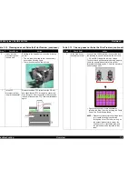
Figure 4-4. Removing Each Circuit Board
Figure 4-5. Setting the Cables to Holders A and B
C A U T I O N
n
Since the CN10 is a locking connector, be sure to release
the locks before removing the cables.
Also, make sure to lock them when connecting the cable.
C298PSB/PSE
Board
C298MAIN Board
Shield Plate M/B
Assembly
Earth Plate
No1. Screws
No5. Screws
No1. Screws
A D J U S T M E N T
R E Q U I R E D
Be sure to perform the following adjustments after replacing
the Main Board;
1.
Head voltage ID Input (Refer to Chapter 5.)
2.
Bi-D adjustment, including Head Gap Adjustment (Refer
to Chapter 5.)
3.
USB ID data input (Refer to Chapter 5.)
Be sure to exchange the following parts also when replacing
the Main Board;
1.
Waste Ink Absorption Pad
2.
Ink Cartridge (BK & Color)
This parts exchange is required since the several ink
counters stored in the EEPROM are lost when the Main Board
is replaced.
C H E C K
P O I N T
Make sure each cable is set in the correct cable holder (A or
B) on the M/B Shield Plate. Refer to Figure 4-5.
Cable Holder B
ASF HP Sensor Cable
CR, PF Motors
PE Detector
Cable
Head FFC
CR Encoder Sensor FFC
Panel
FFC
Cable Holder A
Содержание Stylus COLOR 1160
Страница 8: ...C H A P T E R PRODUCTDESCRIPTION ...
Страница 28: ...C H A P T E R OPERATINGPRINCIPLES ...
Страница 53: ...C H A P T E R TROUBLESHOOTING ...
Страница 74: ...C H A P T E R DISASSEMBLYANDASSEMBLY ...
Страница 116: ...C H A P T E R ADJUSTMENT ...
Страница 150: ...C H A P T E R MAINTENANCE ...
Страница 160: ...APPENDIX C H A P T E R ...
Страница 171: ...PSON Stylus COLOR 860 1160 Revision C ppendix Circuit Board Component Layout 171 Figure 7 5 C298PNL Component Layout ...


