


8 Precautions
S5U1C17001H USER MANUAL
Seiko Epson Corporation
21
(ICDMINI VER1.0 and VER1.1)
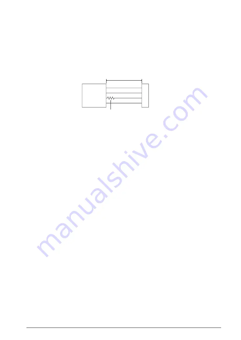
Wiring between the S1C processor and target connector
When wiring the S1C processor to the target connector for connecting the S5U1C17001H, insert a 33
W
resistor in series between the S1C processor DSIO pin and the connector. This resistor must be placed as
close to the S1C processor as possible. If the reset line is not connected, the system can be operated without
this 33
W
resistor. However, we recommend inserting this resistor to prevent malfunctions. The other pins are
connected directly. The total length of the line must be under 5 cm. A low-level input to the DSIO pin issues
a forced break to set the S1C processor into debug mode. Although this signal is pulled up through about 100
k
W
internally, when not debugging, we recommend either removing the 33
W
resistor to reduce noise and other
problems or pulling this line up to the V
DD
level.
S1C processor
DCLK
GND
DSIO
DST2
Target
connector
Within 5 cm
Place a 33
Ω
resistor in series at a location
as close to the S1C processor as possible.
Figure 8.3.1 Wiring between S1C Processor and Target Connector
Reset request
Do not reset the target system while the target program execution is suspended as the S5U1C17001H will be
unable to operate normally.
Notes on target system’s interface
The allowable voltage range for the signals input from the target system is 0 to 5.0V for Ver 1.0 and 0 to 5.5V
for Ver 1.1. The S5U1C17001H may fail if voltages that exceed this range are input. Therefore, target systems
to be connected to the S5U1C17001H must be designed so that voltages outside this range are not applied. Take
special care in designing the target system power supply, and design the target system so that overvoltages are
not applied to the S5U1C17001H when the target system power supply is turned on or off.