


Installation and Configuration
12
Seiko Epson Corporation
S5U13706B00C Rev. 1.0 Evaluation Board
Rev. 5.1
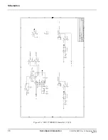
JP6 - LCD Panel Voltage
JP6 selects voltage level to the LCD panel.
Position 1-2 sets the voltage level to 5.0V (default setting).
Position 2-3 sets the voltage level to 3.3V.
Note
When configured for Sharp HR-TFT or Epson D-TFD panels, JP1 must be set to no
jumper and JP6 must be set to position 2-3.
Figure 3-7: Configuration Jumper (JP6) Location
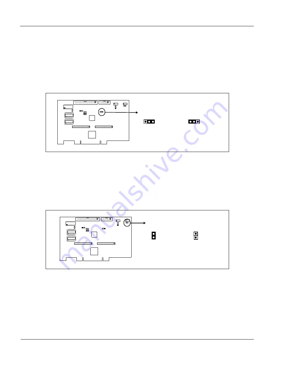
JP7 - Contrast adjust for -ve LCD bias (VLCD)
JP7 selects the type of control used for contrast adjustment of the -ve LCD bias (VLCD).
Position 1-2 selects software control of the contrast adjustment.
Position 2-3 selects manual control of the contrast adjustment using potentiometer R31
(default setting).
Figure 3-8: Configuration Jumper (JP7) Location
JP6
5.0V
3.3V
JP7
Software
Control
Manual
Control


