27 GRAPHICS ENGINE (GE)
27-14
Seiko Epson Corporation
S1C33L26 TECHNICAL MANUAL
To support various built-in RAM LCD panels via the USIL module, TF_TYPE/GE_DISP_CFG register is pro-
vided to configure the transfer data type. For more information on the data types, see the GE_DISP_CFG regis-
ter description in the “Control Register Details” section.
Drawing Effects
27.3.5
A command argument (Effect Setting) is provided to specify drawing effects to apply when the GE module ex-
ecutes a drawing command to draw an object/image on the work area.
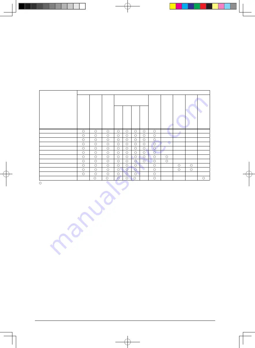
Table 27.3.5.1 lists the effects supported by the commands.
3.5.1 Drawing Effects Supported by Commands
Table 27.
Drawing command
Drawing effect (Effect Setting parameters)
Clipping
(Clip Enab
le)
Transparenc
y
(T
ransparent Enab
le)
Sync with LCD displa
y
(Sync Enab
le)
Writing effect
(Write Effect Setting)
P
alette con
ver
sion
(P
alette Select)
Ar
c/cir
cular section
(1/8 P
osition Select)
Resizing/tiling
(Resiz
e/Tile Select)
Rotation
(Rotation Select)
Transf
er sour
ce/
destination
(Memor
y Area Select)
Normal (Fill)
XOR
Mesh
Re
write
Dot
–
–
–
–
Straight line
–
–
–
–
Rectangle
–
–
–
–
Solid filled triangle
–
–
–
–
Solid filled rectangle
–
–
–
–
Solid filled quadrilateral
–
–
–
–
Circle
–
–
–
Solid filled circle
–
–
–
Character
–
–
–
Decompression
–
–
–
Copy
–
–
–
–
–
Block transfer
–
*
*
*
–
–
–
–
: Can be specified. –: Cannot be specified.
*
: The block transfer command supports these effects only when data is transferred from a memory to VRAM.
These effect cannot be used when data is transferred from VRAM to a memory.
The following describes the drawing effects individually.
Clipping
The clipping function can be enabled or disabled.
Clip Enable bit = 1: Clipping enabled
Clip Enable bit = 0: Clipping disabled
When the clipping function is enabled, the GE draws only within the clipping area (see Section 27.3.1) config-
ured with the GE_CLIP_ST and GE_CLIP_END registers. When disabled, the GE can draw across the whole
work area.
Transparency
Transparency can be enabled or disabled.
Transparent Enable bit = 1: Transparency enabled
Transparent Enable bit = 0: Transparency disabled
When transparency is enabled, the pixels with the transparent color specified in objects/images are not drawn
on the work area and the current pixel color is left unchanged.
The transparent color must be set to MAGIC_COL[15:0]/GE_MAGIC register in advance. A color within the
effective range for the bpp mode (set using DISP_BPP[2:0]/GE_DISP_CFG register) can only be specified.
Note that transparent color comparison is performed with the pixel color after being converted via CCT.


