3. Setup of Software Development Environment
S1C31 Family Software Development
Seiko Epson Corporation
9
Setup Guide (Rev.4.0)
3.3.2
When Using the J-Link
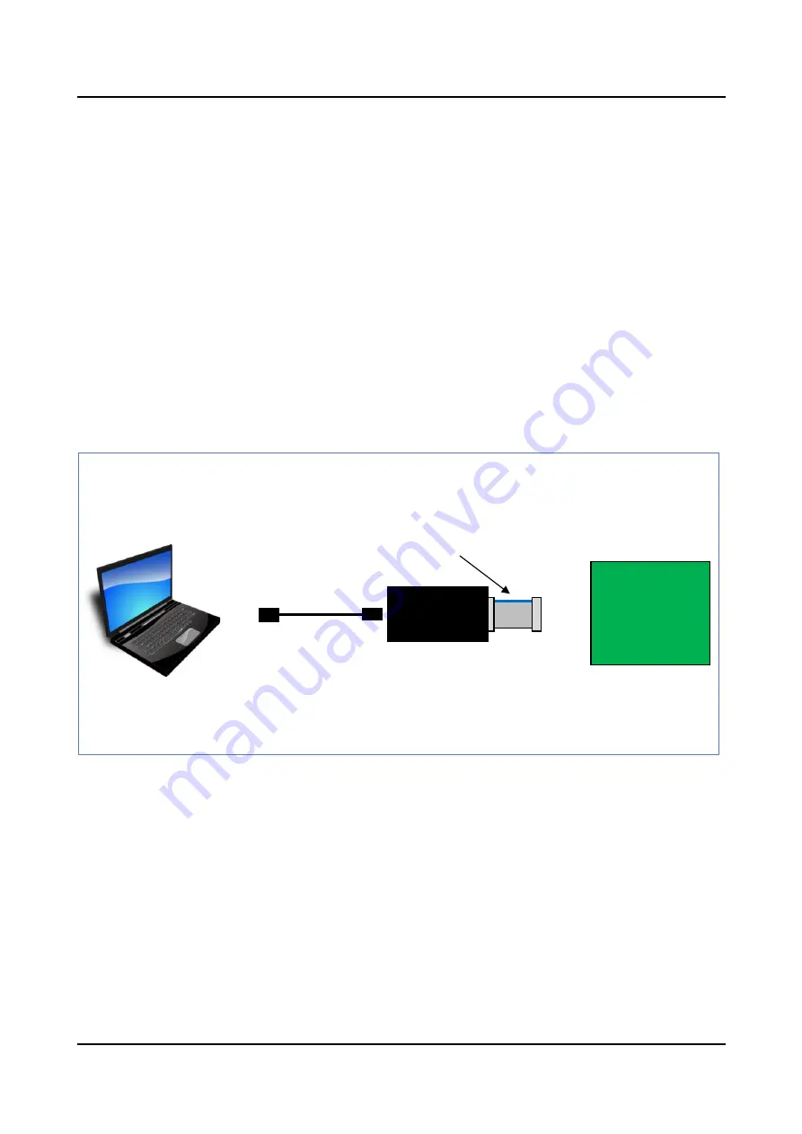
(1) Connect J-Link to the PC with either IAR EWARM or MDK-ARM installed, using the USB cable included
with J-Link. This enables the PC to automatically install the device driver.
(2) Connect J-Link to the evaluation board(ex. S5U1C31xxxTx) using ribbon cable included with J-Link. (see
Figure 3.3.2.1)
(3) When supply the 5V power supply from J-Link to the evaluation board, set up J-Link in the following
procedure. When supplying the power to the evaluation board with the external power supply, the following
procedure is unnecessary.
(3.1) Download “J-Link Software and Documentation Pack” of Ver.6.xx or later from the SEGGER
website.
(3.2) Click “J-Link Software and Documentation Pack (*.exe)” to install it.
(3.3) Click [SEGGER – J-Link V6.xx > J-Link Commander V6.xx] in the start menu on Windows. Then
the console screen will be displayed. (see Figure 3.3.2.2)
(3.4) Enter the following commands into the console screen.
J-Link> power on perm
J-Link> exit
Figure 3.3.2.1 Hardware Connection using J-Link
*1
*1: Figure 3.3.2.1 shows an example when the evaluation board (S5U1C31xxxTx) works using 5V power supply
supplied from a debug probe (J-Link).
Evaluation
Board
(S5U1C31xxxTx)
J-Link
(SEGGER)
Ribbon cable included
with J-Link
USB cable with J-Link


