9. Electrical Characteristics
RX8130CE
Jump to
ETM50E-07
Seiko Epson Corporation
13
9.2.
AC characteristics
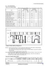
Table 7 AC characteristics
Unless otherwise specified GND = 0 V V
IO
= 1.6 V ~5.5 V Ta = -40
C ~ +85
C
Item
Symbol
Standard-Mode
(f
SCL
=100 kHz)
Fast-Mode
(f
SCL
=400 kHz)
Unit
Min.
Max.
Min.
Max.
SCL clock frequency
f
SCL
100
400
kHz
Start condition setup time
t
SU;STA
4.7
0.6
s
Start condition hold time
t
HD;STA
4.0
0.6
s
Data setup time
t
SU;DAT
250
100
ns
Data hold time
t
HD;DAT
0
0
ns
Stop condition setup time
t
SU;STO
4.0
0.6
s
Bus idle time between
start condition and stop condition
t
BUF
4.7
1.3
s
Time when SCL =
"L"
t
LOW
4.7
1.3
s
Time when SCL = "H"
t
HIGH
4.0
0.6
s
Rise time for SCL and SDA
t
r
1.0
0.3
s
Fall time for SCL and SDA
t
f
0.3
0.3
s
Allowable spike time on bus
t
SP
50
50
ns
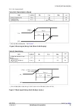
Timing chart
t
HD ; DAT
t
SU ; DAT
t
HD ; STA
t
LOW
t
HIGH
1 / f
SCL
t
r
t
f
t
SU ; STA
SDA
SCL
START
CONDITION
(S)
BIT 7
MSB
(A7)
BIT 6
(A6)
ACK
(A)
Protocol
t
BUF
t
SU ; STO
STOP
CONDITION
(P)
START
CONDITION
(S)
(P)
(A)
t
HD ; STA
t
SU ; STA
(S)
BIT 0
LSB
(R/W)
(S)
t
SP
Figure 9 I
2
C-Bus Interface Timing Chart
Warning: When accessing this device, all communication from transmitting the start condition to transmitting the
stop condition after access should be completed within 0.95 seconds.
If such communication requires 0.95 seconds or longer, the I
2
C-Bus interface is reset by the internal bus
timeout function.
When bus-time-out occur, SDA turns to Hi-Z input mode.
Note: During access to the time registers, the time counting is on hold.
This means that up to 1 second can be “lost”
in case of unsuccessful communication as mentioned above.
Please make sure to send I
2
C start condition before actual transmission of the RTCs slave address as
otherwise the slave address appears to be shifted by 1 bit.
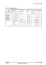
Table 8 AC characteristics (FOUT)
※
Unless otherwise specified GND = 0 V , V
IO
= 1.6 V
5.5 V , Ta=
40
C
+85
C
Item
Symbol
Condition
Min.
Typ.
Max.
Unit
FOUT symmetry
SYM
50% V
IO
Level
40
60
%


