


14. How to use
RX4111CE
Jump to
ETM62E-02
Seiko Epson Corporation
28
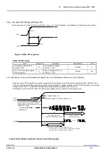
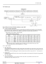
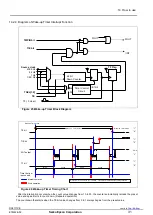
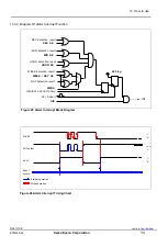
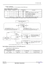
Block diagram of Inside counter of wake-up Timer.
4096 Hz
Resister
Timer Counter 0
Timer Counter 1
Timer Counter 2
TSTP
source
clock
selector
64 Hz
1 Hz
1/60
1 Hz
1/60 Hz
TSTP
timer stop signal
TSTP,TBKE,TBKON bit
Source clock select signal
TSEL0,TSEL1 bit
The resolution of the count value depends on the source clock.
Figure 21 Wake-up Timer Block Diagram (timer source)
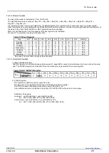
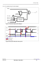
3) TE bit
(Timer Enable)
When TE bit is 0, the default (preset) can be checked by reading this register.
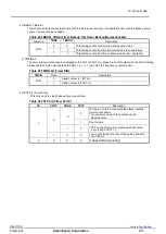
Table 21 TE bit (Timer Enable)
TE
Data
Description
Write
0
Stops Wake-up timer interrupt function.
Timer load the preset value and stop.
1
Starts Wake-up timer interrupt function.
The countdown that starts when the TE bit value changes from 0
to 1 always begins from the preset
value.
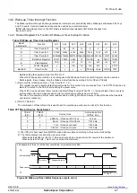
4) TF bit
(Timer Flag)
This is a flag bit that retains the result when a Wake-up timer interrupt event is detected.
Table 22 TF bit (Timer Flag)
TF
Data
Description
Write
0
The TF bit is cleared to zero to prepare for the next status detection
1
Invalid. writing a 1 will be ignored
Read
0
Wake-up timer interrupt events are not detected.
1
Wake-up timer interrupt events are detected.
(Result is retained until this bit is cleared to zero.)
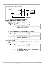
5) TIE bit
(Timer Interrupt Enable)
This bit is used to control output of interrupt signals from the /INT pin when a Wake-up timer interrupt event has
occurred.
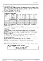
Table 23 TIE bit (Timer Interrupt Enable)
TIE
Data
Description
Write
0
1) The Wake-up Timer interrupt signal is not output.
2) The time wake-up Timer interrupt signal during output is immediately
released.
Note. as for INT-pin, Alarm, Wake-up Timer and Time update interrupts are
output as OR.
1
When a Wake-up timer
interrupt event occurs, an interrupt signal is generated
(/INT status changes from Hi-z to low).


