background image

EPSON PhotoPC 800

Revision A

Disassembly and Assembly

Disassembly and Assembly

59

4.2.0.1  Cabinet Parts Removal

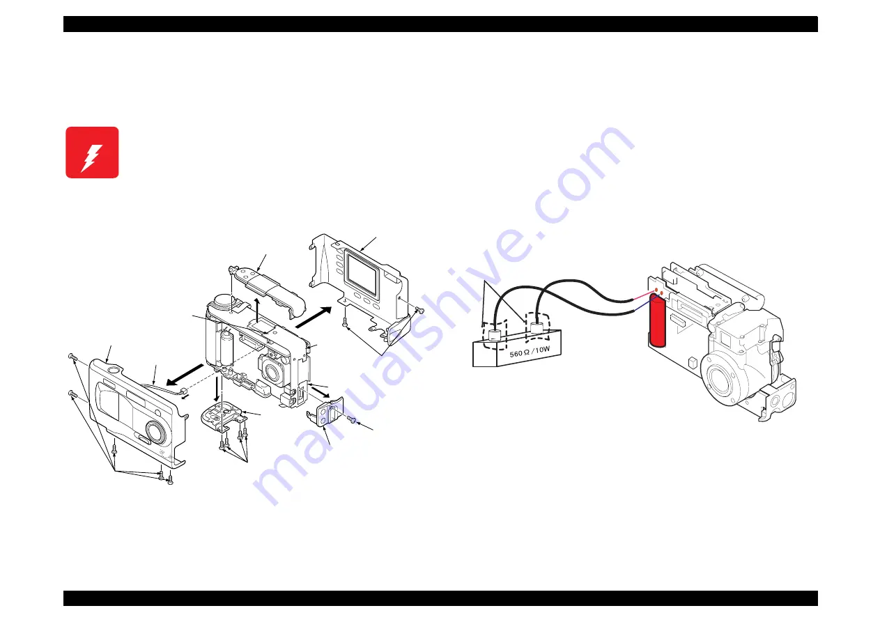
The figure 4-2 shows disassembling of Cabinet Assembly (Rear, Front and 
Top), Cover Battery and Cover CF. When removing the parts, follow the 
number in the figure as procedure order.

Figure 4-2.  Cabinets Parts Removal

4.2.0.2  Releasing the electricity from the Capacitor

Following shows how to release the electricity from the electrolytic capacitor 
(C5412) on the PW1 board. If you don’t perform this, you will get a high chance 
of getting electric shock. Follow the procedures below.

1.

Have a cement resistance, which has a standard higher than 560

 /10 W.

2.

After removing the front cabinet of the camera, connect 2 lead wires to the 
soldering wires of the electrolytic capacitor. (There is no determined poles) 

Figure 4-3.  Releasing electricity of the capacitor

W A R N I N G

There is a danger of getting electric shock from the 

electrolytic capacitor (C5412) mounted on the PW1 
board. Discharge the electricity by using the cement 
resistance when you need to touch PW1 board for 
repair service. (See the next section)

1.Screw 1.7x4

2.Cabinet Back

1.Screw1.7x4

8.Screw1.7x4

7.Holder Terminal

6.Screw1.7x4

10.Remove the 

solder

12.Shield 

tape

5.Cabinet top

11.Remove the tape 

on the rear side.

4.Cabinet front

3.Connector

9.Cover 

battery

JEP-1

No fixed 

direction

Avoid getting electric 

shock by using insulating 

Use the resistance at 

least 560ohm/10W.

dis02

Содержание PhotoPC 800

Страница 1: ...EPSONPhotoPC800 Digital Still Camera SEDC99002 6 59 0 18 6 59 0 18 6 59 0 18 6 59 0 18 ...

Страница 2: ...e contents of this manual However should any errors be detected SEIKO EPSON would greatly appreciate being informed of them The above not withstanding SEIKO EPSON CORPORATION can assume no responsibility for any errors in this manual or the consequences thereof EPSON is a registered trademark of SEIKO EPSON CORPORATION General Notice Other product names used herein are for identification purpose o...

Страница 3: ...NOT CONNECT THE UNIT TO A POWER SOURCE UNTIL INSTRUCTED TO DO SO WHEN THE POWER SUPPLY CABLE MUST BE CONNECTED USE EXTREME CAUTION IN WORKING ON POWER SUPPLY AND OTHER ELECTRONIC COMPONENTS WARNING 1 REPAIRS ON EPSON PRODUCT SHOULD BE PERFORMED ONLY BY AN EPSON CERTIFIED REPAIR TECHNICIAN 2 MAKE CERTAIN THAT THE SOURCE VOLTAGES IS THE SAME AS THE RATED VOLTAGE LISTED ON THE SERIAL NUMBER RATING PL...

Страница 4: ...CT DESCRIPTIONS Provides a general overview and specifications of the product CHAPTER 2 OPERATING PRINCIPLES Describes the theory of electrical and mechanical operations of the product CHAPTER 3 TROUBLESHOOTING Provides the step by step procedures for troubleshooting CHAPTER 4 DISASSEMBLY AND ASSEMBLY Describes the step by step procedures for disassembling and assembling the product CHAPTER 5 ADJU...

Страница 5: ...Revision Status Revision Issued Date Description A June 10 1999 First Release ...

Страница 6: ...ircuit Description 41 SY1 Circuit Description 43 PW1 Power Circuit Description 48 Trouble Shooting Overview 53 Troubleshooting 53 Camera has no power 53 No Shooting 54 Image can not be taken 54 Disassembly and Assembly Overview 56 Precautions 56 Equipment and Tools 57 Disassembly and Assembly 58 Assembly Procedure 63 Assembling the Lens Assembly 63 Earth Terminal installation between CA2 PW1 Board...

Страница 7: ...CD Panel Adjustment 85 LCD H AFC Adjustment 86 Uploading the Firmware 88 Maintenance Preventive Maintenance 91 Check Points 91 Appendix Connections among Boards 93 Component Layoust of Circuit Boards 94 Circuit Shematics 99 Exploded Diagram 106 Simens Star Chart 109 ...

Страница 8: ... 3 7 5 4 PRODUCT DESCRIPTION ...

Страница 9: ... Continuous shooting Interval shooting VF View Finder shooting mode LCD shooting mode Auto Manual Digital Zoom Panorama Macro Monochrome Good for sports portrait and landscape shooting Able to change the Shutter Speed Focus value Shooting function Automatic predefined and adjustable exposure settings 2 0 to 2 0EV in increments of 0 5 White balance custom fixed auto Built in microphone for audio re...

Страница 10: ...s Turning image function Thumb nail indication Auto photo fine function Uploading the audio recordings Direct printing software Optional Software for Direct Printing The program Direct Print Ver 3 0 for direct printing comes with Photo PC800 Function Image printing Album printing Index printing Sticker printing Image information printing Auto photo fine printing Supported Printer EPSON Stylus Phot...

Страница 11: ...xterior View Product Name Code No Computer printer Specification Connection Cable for Mac direct printing CPCB1 Macintosh with printer board or modem board Camera Side Exclusive connector Computer side MiniDin 8 pin EPSON Stylus color series printer Stylus Photo EX Stylus Photo Stylus Photo 1200 700 and 750 Stylus Color 740 Camera Side Exclusive connector Computer side MiniDin 8 pin Cable for DOS ...

Страница 12: ...e Aperture f2 4 f8 0 Focus Auto focus Manual focus NOTE When shooting the object with bad contrast or low light auto focus may not work correctly Especially when the shooting needs a flash set the distance 1 5 cm forcefully Sensitivity Equivalent to ISO 100 200 400 Shutter Electric iris with mechanical shutter 1 30 second to 1 750 second auto flash and forced flash modes 1 2 second to 1 750 second...

Страница 13: ...KB second At each mode DRAM is available up to 4MB Up to 10 pictures Continuous shooting Full size 1 image second VGA 2 images second Continuous shooting is available up to 4MB in the RAM Flash is set Off forcibly Beeping sound available per shooting Digital zoom 2 x digital zoom Image size of the each recording mode is available Panorama 1600 x 600 Super fine Fine Monochrome 1600 x 1200 Super fin...

Страница 14: ...een light blink Orange light blink Off Built in clock Year Month Date Time Minute Second NOTE However Timer IC operates when the battery is installed When the batteries are exchanged the time will be kept counted for 30 minutes until the the electricity in the capacitor runs out Power Saving Function Available to select the power save off time between 10 sec 30 sec 1 min or 3 min 10 seconds Shuts ...

Страница 15: ...nds 1 min 3 minutes none Camera brightness adjustment 3 3 7 levels Beep sound On Off Audio recording setting None 3 seconds 5 seconds 10 seconds White balance setting Memory setting Directory selection Adding the expansion function Initializing the memory card V F SHOOTING MODE Using the viewfinder when taking helps save battery power and can make it easier for the user to hold the camera steady w...

Страница 16: ...tal zoom x2 Macro Panorama Sensitivity Standard High sensitivity Super High Auto fixed or custom white balance Exposure correction 2 2 at intervals of 0 5 9 step Various program shooting sports portrait landscape normal Aperture priority shooting F2 4 F8 Exposure control Divided brightness metering Program Auto Spot metering Program Auto Audio recording Manual For experienced users who want comple...

Страница 17: ... feature Time lapse feature interval shooting Shooting interval time setting 10 seconds Min interval 24 hours Max interval Setting is available every 1 second When using the audio recording or HyPict features the shortest time interval available is 20 seconds instead of 10 Except for using the audio recording and HyPict features 10 seconds 24 hours time interval setting is available by every 1 sec...

Страница 18: ...hoto NOTE If you attach an audio recording to a photo saved in your memory card the number of photos you can save on that card may decrease Figures in the table represent storage capacity when there is no image data in the internal memory If other file is stored in the memory available storage capacity decreases according to the file volume Time seconds Interval time for quick shooting Replay time...

Страница 19: ...printer and modem 19 2 Kbps or higher is required for connecting with the host computer Table 1 6 Interface specification Connector 14 pin dual line terminal Detection function for the plug insertion Table 1 7 Signal Name for Serial Communication Interface Standard Synchronism Communication speed Transmission speed RS 232C Asynchronous Asynchronous 8bit Non Parity 19200 38400 115200 57600 230400 b...

Страница 20: ...t be used Although Alkaline battery can be used it is not recommended AC adapter DC3 4V Input power supply 3 4V 2 5V Battery Life when using two of the included Ni MH batteries Table 1 8 Battery Life Mode Available pictures Approximate Taking photos with View Finder More than 850 pictures Taking photos with LCD monitor Automatic shut off is set to 10 seconds 100 pictures Playing back photos 55 min...

Страница 21: ...Panel Resolution switch Flash switch Self timer switch Name Functions Dial switch Power and setting switch 7 mode rotary switch Special shooting mode Continuous interval shooting LCD shooting mode VF shooting mode OFF Playback mode Expansion function mode PC connection mode SETUP mode Shutter switch 2 step shutter Release button Resolution switch Image quality H Flash switch Flash setting Auto For...

Страница 22: ... correction Displays exposure correction value and aperture value Image Quality Displays image quality Hyper Displays Hypict mode Monochrome Monochrome shooting Self timer Indicates when the self timer is set Flash Indicates flash status Number of pictures remaining When shooting No of pictures remaining and No of pictures stored in the buffer Half shutter Shutter speed White Balance LowBattery ic...

Страница 23: ... orange Shooting Lamp green Timer Lamp red Ready ON Focus Blink 0 2s Flocus lock ON VF shooting when the lens cover is closed Blink 0 8s Shuts down after the lamp blinks 9 times X X LCD Special shooting when the lens cover is closed During CF transmission Blink 0 8s X X Unable to write CF Full Blink 0 8s X X Connecting the AC adapter ON Battery warning Blink 1 0s Err ON X X Self timer on ON Fast b...

Страница 24: ...d Dial switch OFF Dial switch operation during shooting mode Power saving function Shut down when the battery power is low Replacing batteries Effective Super capacitor Replacing batteries invalid super capacitor Panorama Macro O O VF X O O O X Image quality setting include Hypict O O O O O X Flash X Auto O O X X to normal shooting X Quick shooting O O O X transmits the buffer to CF X X Interval s...

Страница 25: ...tor Replacing batteries invalid super capacitor Panorama Macro O O VF X O O O X Image quality setting include Hypict O O O O O X Flash O O O X X X Quick shooting O O O X transmits the buffer to CF X to normal shooting X Interval setting O O VF X O X X X SET UP setting O O O O O X Priority mode X O VF X O X X X W B O O O O O X W B CUSTOM setting O O O O O X Divided brightness metering Spot metering...

Страница 26: ...tteries invalid super capacitor Panorama Macro O O VF none O O O X Image quality setting include Hypict O O O O O X Flash O O O O O X Quick shooting O O O X transmits the buffer to CF X to normal shooting X Interval setting O O VF X O O O X SET UP setting O O O O O X Priority mode O O O O O X ME shooting O O O O O X W B O O O O O X W B CUSTOM setting O O O O O X Divided brightness metering Spot me...

Страница 27: ...ing shooting mode Power saving function Shut down when the battery power is low Replacing batteries Effective Super capacitor Replacing batteries invalid super capacitor Slide setting O O O O O X Dial switch OFF Dial switch operation during shooting mode Power saving function Shut down when the battery power is low Replacing batteries Effective Super capacitor Replacing batteries invalid super cap...

Страница 28: ...tion Cable for DOS V Length 1 5m Connector Camera side 14 pin dual line terminal female PC side 9 pin D SUB female Figure 1 5 DOS V Cable 1 5 1 2 Connection Cable for Macintosh Length 1 5m Connector Camera side 14 pin dual line terminal female PC side 8 pin mini DIN male Figure 1 6 Macintosh Cable Camera side PC side ...

Страница 29: ... 29 1 5 1 3 USB Interface Cable Length 1 5m Connector Camera side 14 pin dual line terminal PC side USB Figure 1 7 USB interface cable 1 5 1 4 Video Cable Length 1 5m Connector mini pin RCA 1 5 2 Other accessories Soft camera case TBD Strap Camera side USB iMac ...

Страница 30: ... MH BATTERY CHARGER Model name EU 38 Input AC100 240V 50 60Hz Output DC1 2V 490mA x 4 Compatible batteries EPSON Ni MH Batteries Model EU 24 Charging time 4 batteries Approx 3 5H 1 7 Environmental Condition OPERATING STORAGE ENVIRONMENT Temperature Operating 5 to 35 C Storage 20 to 60 C Humidity Operating 30 to 90 without condensation Storage 10 to 90 without condensation Shock resistance Storage ...

Страница 31: ...rt B class B Canada CSA C108 8 class B Europe EMC Directive 89 336 EEC CE marking EN5502 Class B EN61000 3 2 when using the AC adapter EN61000 3 3 when using the AC adapter EN5 0082 1 IEC801 2 IEC801 3 IEC801 4 Europe EN 55022 CISPR Pub 22 class B Australia AS NZS 348 class B Taiwan EMI CNS13438 C6357 RELIABILITY Flash Memory Life 10K cycles write for Flash Memory ...

Страница 32: ... 3 7 5 5 OPERATINGPRINCIPLE ...

Страница 33: ...nel display Manages and back up the clock Manages power circuits Controls the charging for flash CA1 CCD image sensor interline type CCD clock drive A D conversion of image data Drives Lens ASSY CA2 32 bit RISC CPU driven at 72 MHz ASIC Flash ROM SDRAM γ correction Color signal generation SDRAM control USB control A D conversion of 10 bit audio data Color LCD monitor control PW1 Power supply circu...

Страница 34: ...ision A Operating Principle Operating principles of the Circuit Boards 34 2 2 Operating principles of the Circuit Boards The figure below shows the block diagram of all boards in PhotoPC 800 Figure 2 2 Block Diagram Subject ...

Страница 35: ...block diagram of CA1 board Figure 2 3 CA1 Circuit Block Diagram 2 2 1 2 IC903 Specification of the CCD charged Coupler Device is shown below Structure CCD Image Sensor Interline type Optical size 1 2 inch format Cell pitch 3 95 µm Effective pixel 1650 H x 1250 V Total pixel 1704 H x 1255 V Optical Black Horizontal H direction Front 2 pixel Rear 52 pixel Vertical V direction Front 3 pixel Rear 2 pi...

Страница 36: ... Horizontal Register Vertical Register Terminal Terminal symbol Terminal function Waveform Voltage 1 0D Circuit power supply DC 13V 2 19 GND GND GND 0V 3 0FD Board Clock DC Approx 6 9V Different from every CCD 4 PW Protection transistor bias DC 7V 5 RS Rest gate clock 7V 13V 8 H1 Horizontalregister transfer clock 0V 5V 10 H2 Horizontalregister transfer clock 0V 5V 11 V4 Vertical register transfer ...

Страница 37: ...utput from IC102 is used as the sweep pulse for the electronic shutter and the RG signal which is output from IC102 is the reset gate clock Figure 2 6 IC902 Block Diagram Figure 2 7 IC904 Block Diagram 2 2 1 4 IC905 CDS AGC Circuit A D Converter The video signal which is output from the CCD is input to Pins 26 and 27 of IC905 There are S H blocks inside IC905 generated from the XSHP and XSHD pulse...

Страница 38: ...o the floating diffusion Here the electric charges are converted into voltage at the rate of V Q C by the equivalent capacitance C of the floating diffusion RG is then turned on again by the timing in 1 when the H1 potential becomes deep Thus the potential of the floating diffusion charges in proportion to the quality of transferred electric charge and becomes CCD output after being received by th...

Страница 39: ...rive The four control signals FIN1 FIN2 FIN3 and FIN4 with different phases which are output from the ASIC are converted into drive pulses FOUT1 FOUT2 FOUT3 and FOUT4 by the motor driver IC953 and are then used to drive the stepping motor for focusing operation Detection of the standard focusing positions is carried out by means of the photointerruptor FOCUS PI inside the lens block Table 2 5 Focu...

Страница 40: ...EPSON PhotoPC 800 Revision A Operating Principle Operating principles of the Circuit Boards 40 Figure 2 11 Lens Drive Circuit Block Diagram Shutter Motor Iris Motor Focus Motor ...

Страница 41: ... the CPU and color generation is carried out Each pixel is interpolated from the surrounding data as being either Ye Cy Mg or B primary color data to produce R G and B data At this time correction of the lens distortion which is a characteristic of wide angle lenses is carried out After AWB and γ processing are carried out a matrix is generated and aperture correction is carried out for the Y sign...

Страница 42: ...circuit generates the Y signals R Y signals and B Y signals from the RGB signals Horizontal and vertical aperture circuit This circuit is used generate the aperture signal AE AWB and AF computing circuit The AE AWB carries out computation based on a 64 segment screen and the AF carries out computations based on a 6 segment screen SDRAM controller This circuit outputs address RAS CAS and AS data fo...

Страница 43: ... a Y C signal the data is sent to the LCD panel and displayed The two analog signal Y C signals from the ASIC are converted into RGB signals by the LCD driver and these RGB signals and the control signal which is output by the LCD driver are used to drive the LCD panel The RGB signals are 1H transposed so that no DC component is present in the LCD element and the two horizontal shift register cloc...

Страница 44: ...put terminal external register connection 31 VSS GND 32 49 S1 S18 O LCD segment output 1 19 50 55 NOT USED O 56 NOT USED O Connect to GND Pin Signal Name I O Outline 57 59 SCAN IN4 6 I Keymatrix input 64 WAKE UP O SPARC Wake up terminal 65 69 NOT USED O Connect to GND 70 PA ON O DC DC converter analog ON OFF signal H ON 71 P ON O DC DC converter digital O OFF signal H ON 72 DIN CONNECT I PC cable ...

Страница 45: ...outputs this data to the camera circuits ASIC or to the LCD display device as operation mode setting data The figure below shows the internal communication between the 8 bit microprocessor ASIC and SPARC lite circuits Figure 2 14 Internal Bus Communication System Pin Signal Name I O Outline 91 94 SCAN OUT 0 3 O Key matrix output 95 LCD ON O DC DC converter LCD system ON OFF signal H ON 96 ASIC TES...

Страница 46: ...y for the battery to be attached again When a switch is operated the 4 bit microprocessor supplies power to the system as required The 8 bit microprocessor first sets both the P A ON signal at pin 71 and the P A ON signal at pin 70 to high and then turns on the DC DC converter After this High signals are output from pins 97 and 88 so that the ASIC and the SPARC lite are set to the active condition...

Страница 47: ...CD 8bit CPU MODE LCD LCD MONIT OR C A M Power switch ON Auto power down OFF OFF OFF OFF OFF 4MHz ON OFF Shutter switch ON ON ON OFF OFF ON OFF 4MHz OFF OFF Resoluti on Flash Self timer switch ON OFF OFF OFF OFF OFF 4MHz ON OFF LCD SPECIAL ON ON ON ON ON 4MHz ON ON PLAY ON ON ON ON OFF 4MHz ON ON DIRECT PRINT ON ON ON ON OFF 4MHz ON OFF SET UP ON ON ON ON OFF 4MHz ON ON ...

Страница 48: ...locks Switching controller IC501 IC502 Digital and analog system and LCD 5 0 V system power output L5010 Q5002 D5013 C5061 Digital 3 3V system power supply L5017 Q5006 D5004 C5062 Digital 3 4V system power supply L5001 Q5006 D5004 C5060 Analog and LCD system power supply Q5007 T5001 Back light power supply output L5005 Q5008 D5014 C5005 Figure shows PW1 circuit block diagram Figure 2 15 PW1 Circui...

Страница 49: ...l 5 5V L power supply outputs are received and the PWM duty is varied so that each one is maintained at the correct voltage setting level Short circuit protection circuit If output is short circuited for the length of time determined by the condenser which is connected to Pin 2 if IC502 all output is turned off The control signal P ON P A ON and LCD ON are controlled to restore output Digital 3 3V...

Страница 50: ...oltage alternating current by the oscillation transformer Rectifier circuit The high voltage alternating current which is generated at the secondary side of T5401 is rectified to produce a high voltage direct current and is accumulated at electrolytic capacitor C5412 on the main circuit board Voltage monitoring circuit This circuit is used to maintain the voltage accumulated at C5412 at a constanc...

Страница 51: ...Boards 51 W A R N I N G PW1 board has a danger of getting electric shock because of C5412 Hold the edges of this board and never touch the board surface when you handle this board Discharge the charged energy of C5412 for safety before handling this board See Chatper 4 for more details ...

Страница 52: ... 3 7 5 6 TROUBLESHOOTING ...

Страница 53: ...r is disconnected from the plug Electrolytic capacitor C5412 mounted on the PW1 board is for flash emission This capacitor is charged automatically every time the power is turned on Therefore since there is a possibility to get electric shock during the service operation release the electricity by using the cement resistance if you need to touch the capacitor for repair service See Chapter 4 for m...

Страница 54: ... and shutter switch 3 Check 7 or 8 pin PON P A ON pulse input LOW Check IC301 and PW1 4 Is all 6 17 or 8 pin PON P A ON of CN301 high NO Check IC301 PW1 and CA2 5 Is the serial communication normal NG Check IC301 and CA2 6 Check CA2 Procedure order Check point Judgement Solution 1 Is the system drive clock 72MHz input to 280 pin CLK IN1 of IC102 YES Check X1101 IC111 2 Is CLK 36MHz input to 132 pi...

Страница 55: ... 3 7 5 7 DISASSEMBLYANDASSEMBLY ...

Страница 56: ...The performance of the second maintenance is allowed to be done only by the service center equipped with special instrument for adjustment We do not guarantee the repair result by the others Refer to the table 4 1 for distinction between first and second maintenance Refer to Table4 1 and 4 2 Use the exclusive package material when transporting a camera No Service Performed Required Adjustment Main...

Страница 57: ... L voltage adjustment 2 8 5 8V L voltage adjustment 9 Lens Adjustment 10 AWB adjustment 11 Color Matrix adjustment 12 CCD Defect Detect adjustment 1st Maintenance Name Note Oscilloscope Higher than 100MHz Digital voltmeter IBM compatible PC Windows 95 or 98 and following conditions should meet CD ROM drive 3 5 inch high density diskette drive Serial port with standard RS 232C interface 8MB RAM Har...

Страница 58: ...d for adjustment C A U T I O N Read Precautions on page 56 before starting disassembly When disassembling the camera follow the order in the figure Remove the cables total 4 cables for prevention of radiation according to your necessity S T A R T C a b i n e t R e m o v a l C A 1 B o a r d R e m o v a l M i c r o p h o n e r e m o v a l L C D m o n i t o r r e m o v a l C o n t r o l P a n e l R e...

Страница 59: ... a standard higher than 560Ω 10 W 2 After removing the front cabinet of the camera connect 2 lead wires to the soldering wires of the electrolytic capacitor There is no determined poles Figure 4 3 Releasing electricity of the capacitor W A R N I N G There is a danger of getting electric shock from the electrolytic capacitor C5412 mounted on the PW1 board Discharge the electricity by using the ceme...

Страница 60: ...gure 4 4 SY1 board and Lens Assy Removal C A U T I O N When assembling the optical filter be careful of its direction since it has a determined direction to be installed See Assembling the Lens Assembly on page 63 A A 1 Screw 1 7 x4 2 Control Panel 5 Screw 1 7x4 13 Connector 12 FPC 3 Open the cover CF 6 Heat sink rubber A Optical filter 11 CA1 board 7 Screw 2x2 5 8 Screw 2x6 10 FPC 9 Remove the so...

Страница 61: ...bly order follow that order Figure 4 5 SY1 board and LCD Removal A D J U S T M E N T R E Q U I R E D When replacing the CA1 board refer to Chapter 5 Adjustment and perform the necessary adjustment B B 5 Connector 11 Connector 10 FPC 12 LCD 9 Holder Monitor 8 Remove the solder 13 Heat sink A 14 Heat sink rubber B 7 Screw 1 7x4 2 Connector 3 Remove the solder 1 Screw 1 7x4 4 Connector 6 SY1 Board JE...

Страница 62: ...ecessary to remove the solder of earth terminal on the CA2 side Figure 4 6 PW1 and CA2 boards Holder Battery and Holder Lens Removal A D J U S T M E N T R E Q U I R E D If you replace the CA2 board or CCD refer to Chapter 5 and perform necessary adjustment C C 8 Screw 1 7x4 1 Screw 1 7x4 2 Stand 4 Earth Terminal 3 Remove the solder 14 Holder lens 6 Screw 1 7x4 9 Connector 10 CA2 board 7 Screw1 7x4...

Страница 63: ...alling the CA1 7 to the guide boss of the holder and the terminal of CCD fix the holder with 2 screws 2x6 Tightening torque 2 0 2 5kgf cm 7 Fix the mounting lens with 1 screw Tightening torque 1 5 2 0kgf cm 8 Solder the CCD to the CA1 board 9 Insert the FPC of lens into the connector of CA1 board 10 Solder the lead wire JW905 to the CA1 board Figure 4 7 Assembling the Lens Assembly C A U T I O N S...

Страница 64: ...l installation between CA2 PW1 Boards 1 Fix the Earth Terminal with Stand to the Holder Lens by one screw 1 7x4 2 Solder the Earth Terminal to the board Figure 4 8 Soldering the Earth Terminal Solder to the land of PW1 CA2 board CA2 LCD PW1 Solder with Shield Tape Stand Screw Earth Terminal dis05 ...

Страница 65: ... that the PB of rubber B can match the PB of the rubber A 4 Solder the lead wire to the corner on the back side of Holder Monitor 5 Fix Holder Monitor with 3 screws 2x5 black Tightening torque 1 3 0 2 kgf cm 6 Fix VF view finder with 2 screws 2x5 black Tightening torque 2 0 0 2 kgf cm 7 Connect the harness of Microphone to the connector of SY1 board then put it between the lens assembly and SY1 St...

Страница 66: ...nnector on the CA1 board NOTE Open the lock of the connector upward completely and insert FPC straight until it stops When you lock it press the both sides of lock and close it Figure 4 10 Lock 3 Fix the lens assembly on the CA1 board with 3 screws 1 7 x 4 Tightening torque 1 3 0 2 kgf cm Figure 4 11 Installing the CA1 Board Lock dis08 Screw 1 7x4 CA1Board Holder Lens dis09 ...

Страница 67: ...he PW1 board and lead the harness to the arrowed direction in the figure Figure 4 13 Back Light Harness NOTE The purpose of forming the harness is not to pinch the harness with the Holder CF 6 Form the harness of buzzer under the SY1 board FPC LCD To CA2 board connector To PW1 board connector Heat sink A Rubber A should be sticked along with the shape of the connector and basing on the its edges S...

Страница 68: ... Buzzer Harness 4 3 6 Installing the Holder CF Fix the Holder CF to the Holder Lens Holder Batt with 3 screws 1 7 x 4 black Tightening torque 1 2 0 2 kgf cm Figure 4 15 Installing Holder CF Form the buzzer harness under the SY1 board dis12 Holder CF Screw 1 7x4 black Holder Battery Holder Lens dis13 ...

Страница 69: ...ld it at the corner of SY1 board 3 Stick 2 Spacer Blind s to the Shield Tape NOTE Refer to the figure below for how to attach the Spacer Blind Figure 4 16 Installing the Spacer Blink 4 Solder the Shield Tape to the Earth Terminal Figure 4 17 Attaching the Shield Tape Shield Tape Spacer Blinds Stick Spacer Blind along with connector edge dis14 Same as Shield Tape Shield Tape Solder to the Earth Ter...

Страница 70: ... of Unit Control Panel to the LCD below 2 Install the Unit Control Panel and fix it with 2 screws 1 7x4 See 2 and 3 in the figure Tightening torque 1 0 0 2 kgf cm 3 Install the dial switch and insert FPC Then fix it with one screw 1 7x4 See 4 in the figure Tightening torque 1 0 0 2 kgf cm NOTE Tighten the screws 2 3 and 4 in that order Figure 4 19 Installing Unit Control Panel Holder CF Cover Batt...

Страница 71: ...y one screw 1 7x4 Tightening torque 1 3 0 2 kgf cm 4 Hang the hook of Holder Terminal on the power supply jack connector of PW board and fix it to the Holder Lens with one screw 1 7x4 black Tightening torque 1 3 0 2 kgf cm 5 Attach the Pad to the Holder battery See Figure 4 21 Figure 4 22 Installing the Holder Terminal Cabinet Top SY1 Board dis18 Holder Battery Pad Shaft Strap DEC Right Screw 1 7x...

Страница 72: ...s of Cabinet Front to the connector of SY1 board then form the harness so that the harness does not hang over the flash Figure 4 24 Forming for Harness of Cabinet Front 8 Install the Cabinet Front 9 Install the block of the camera board to Cabinet Back 10 Fix the bottom of Cabinet Back with 2 screws 1 7x4 Tightening torque 1 6 0 2 kgf cm Pad Mark Mark Note Attaching guide line dis21 dis22 ...

Страница 73: ...2 screws 1 7 x 4 Tightening torque 1 6 0 2 kgf cm 12 Fix Cabinet Front and Cabinet Back with 4 screws 1 7 x 4 Tightening torque 1 6 0 2 kgf cm C A U T I O N When installing the Cabinet Front and Back leave the Cover Battery open Screw 1 7x4 Screw 1 7x4 Screw 1 7x4 Screw 1 7x4 dis23 Cover Battery ...

Страница 74: ... 3 7 5 8 ADJUSTMENT ...

Страница 75: ...nt is done No Service Performed Required Adjustment Maintenance 1 Replacing CA1 Board 1 Initialization 2 AWB 5100K adjustment 3 Color Matrix adjustment 4 CCD Defect Detect Adjustment 5 LCD panel adjustment 6 Lens adjustment Note Follow the order above except the lens adjustment 2nd Maintenance 2 Replacing CA2 Board Same as above 2nd Maintenance 3 Lens 1 Lens Adjustment 2 AWB Adjustment 3 Color Mat...

Страница 76: ...ment 2 8 5 8V L voltage adjustment 9 Lens Adjustment 10 AWB adjustment 11 Color Matrix adjustment 12 CCD Defect Detect adjustment 1st Maintenance W A R N I N G Disconnect the AC adapter or remove batteries before disassembling the camera Discharge the electricity in the electrolytic capacitor C5412 by using the cement resistance The electrolytic capacitor which is mounted on the PW1 board is for l...

Страница 77: ...l port available use port1 to connect your camera 5 Line up the serial connector on the cable with one of serial ports on your computer and insert the connector 6 Turn on the camera and your computer system 7 Insert the calibration software into the disc drive 8 Double click DSCCalDi EXE in the disc and activate the program Figure 5 2 Initial Screen of Adjustment Program AC adapter Serial Cable To...

Страница 78: ...creen when selecting initialization 3 Select Yes and perform initialization A few seconds later the screen below will appear Figure 5 4 Screen when completing the initialization 4 Mark to indicate the camera resolution moves about for 20 seconds Time varies according to the image data size at that time Although mark on the camera body moves slower than the timing of the ending indication on the pr...

Страница 79: ...e barrier switch 3 Set the view mode and turn on the LCD 4 Carry out initialization and display the through image on the LCD screen 5 2 2 1 IC501 Oscillation Frequency Adjustment SETTING Measuring Point CL512 Measuring Equipment Frequency counter ADJ Location VR501 ADJ Value 200 1 kHz Dial switch LCD shooting mode ADJUSTMENT METHOD 1 Adjust with VR501 to 200 1 kHz C A U T I O N Voltage adjustment ...

Страница 80: ...ltmeter ADJ Location VR505 ADJ Value 5 10 0 05V Dial switch LCD shooting mode ADJUSTMENT METHOD 1 Adjust with VR505 to 5 10 0 05 V 5 2 2 4 3 3V D A Voltage Adjustment SETTING Measuring Point CL533 or CL534 Measuring Equipment Digital voltmeter ADJ Location VR503 ADJ Value 3 30 0 03 V Dial switch LCD shooting mode ADJUSTMENT METHOD 1 Adjust with VR503 to 3 30 0 03 V 5 2 2 5 3 4V D B Voltage Adjustm...

Страница 81: ...oltage Adjustment 2 SETTING Measuring Point CL523 or pin 3 of Q5029 Measuring Equipment Digital voltmeter ADJ Location VR506 ADJ Value 12 40 0 05 V Dial switch LCD shooting mode ADJUSTMENT METHOD 1 Set the view mode and turn on the LCD 2 Adjust with VR506 to 12 4 0 05 V 5 2 2 8 5 8V L Voltage Adjustment SETTING Measuring Point CL530 or pin 4 of Q5033 Measuring Equipment Digital voltmeter ADJ Locat...

Страница 82: ...not be used Illumination above the subject should be 400 lux 10 ADJUSTMENT METHOD 1 Set the siemens star chart 95cm 3cm so that it becomes center of the screen 2 Double click on the DscCalDi122 3 Click the Focus and click the Yes Figure 5 7 Button Location of Lens Adjustment Button 4 Lens adjustment value will appear on the screen Appropriate adjustment value is 100 5 Click the OK Serial cable 95 ...

Страница 83: ...ot enter any light 2 Double click on the DscCalDi122 3 Click the AWB and click the Yes Figure 5 9 Button Location of AWB Adjustment Button 4 AWB adjustment values will appear on the screen Appropriate Value Level R Around 213 G 128 fixed value B Around 266 Correction of difference of mechanism shutter Error Condition a0 65535 65535 65535 1023 are indicated when the sampling error occurs 5 Click th...

Страница 84: ...r chart so that it becomes center of the screen 3 Double click on the DscCalDi122 4 Click the UV Matrix and Click the Yes Figure 5 11 Button Location of Color Matrix Adjustment 5 Color matrix adjustment values will appear on the screen Appropriate value level UVMAT0 4 0 255 Error Condition UVMAT0 4 All 1 Iris failure UVMAT0 4 All 2 6 Click the OK Serial Cable Camera Color Viewer 5100K and Color Ma...

Страница 85: ...Defect Detect Adjustment 3 After adjustment is done if any failures are found maximum 16 failures are indicated by x and y coordinates 5 2 7 LCD Panel Adjustment This adjustment should be performed when the CA2 board or is replaced or IC171 on the CA2 board is replaced Figure below shows measuring and adjusting points on the A side of CA2 board Figure 5 13 Positions for measuring and adjusting PRE...

Страница 86: ...ust H AFC so that the time A from the point where the pulse at CL161 rises until the position where the video signal at CL159 starts in 2 9 0 2 µsec Figure 5 14 LCD H AFC Adjustment 5 2 8 1 LCD RGB Offset Adjustment ADJUSTMENT METHOD Adjust LCD RGB offset so that the amplitude of the CL159 waveform is 6 8 V 0 3Vp p Figure 5 15 RGB Offset Adjustment CL161 CL159 A A enlargement CL161 CL159 adj04 CL1...

Страница 87: ...veform is 0 2V with respect to the CL159 VG waveform green Figure 5 17 Blue Brightness Adjustment C A U T I O N LCD Gain Adjustment should be performed after LCD RGB Offset adjustment is carried out LCD RGB Offset Adjustment on page 86 4 2 0 2Vp p CL159 waveform adj06 C A U T I O N LCD RGB Offset adjustment LCD RGB Offset Adjustment on page 86 and LCD Gain adjustment LCD Gain Adjustment on page 87...

Страница 88: ... from SEIKO EPSON to the appropriate hard disk Firmware is usually bin file and compressed 3 Select Firmware on the program 4 File Open Dialog will open since the location were the file is stored is appointed Figure 5 19 Program screen for Firmware Upload 5 Select the new Firmware and press Open C A U T I O N LCD RGB Offset adjustment LCD RGB Offset Adjustment on page 86 and LCD Gain adjustment LC...

Страница 89: ...lash Memory Therefore do not perform other operation until Complete is indicated In the firmware there are 2 types of specification NTSC or PAL Do not upload the firmware for PAL to NTSC or its opposite However there is a protection function on the program When the uploading of Firmware is performed Hyper function Direct Print function and Print mark function are erased at the same time Therefore ...

Страница 90: ... 3 7 5 9 MAINTENANCE ...

Страница 91: ...eck Points Check 1 Is in and out of lens viewfinder free from the finger prints or dirt Also Aren t any power supply cable seen out of viewfinder OK NG 2 Does the dial rotary switch move smoothly and feeling to click OK NG 3 Do you see any dirt or dust in and out sides of flash window OK NG 4 Are the glass surface of the LCD panel on the SY1 board and in and out sides of protection board of the re...

Страница 92: ... 3 7 5 APPENDIX ...

Страница 93: ...EPSON PhotoPC 800 Revision A Appendix Connections among Boards 93 7 1 Connections among Boards Following pages show the connections among boards ...

Страница 94: ......

Страница 95: ...n A Appendix Component Layoust of Circuit Boards 94 7 2 Component Layoust of Circuit Boards Following pages show the component layout of each circuit board CA1 Circuit Board CA2 Circuit Board SY1 Circuit Board PW1 Circuit Board ...

Страница 96: ...ca1_pcb ...

Страница 97: ...ca2_pcb ...

Страница 98: ...sy1_pcb ...

Страница 99: ...pw1_pcb ...

Страница 100: ...EPSON PhotoPC 800 Revision A Appendix Circuit Shematics 99 7 3 Circuit Shematics CA1 Circuit CA2 Circuit NTSC PAL SY1 Circuit PW1 Circuit ...

Страница 101: ......

Страница 102: ...NTSC ...

Страница 103: ...PAL ...

Страница 104: ......

Страница 105: ......

Страница 106: ...EPSON PhotoPC 800 Revision A Appendix Exploded Diagram 106 7 4 Exploded Diagram Following pages show the exploded diagram of PhotoPC800 ...

Страница 107: ...R921 JEP Parts List 1 1 2 3 3 4 5 6 7 8 9 9 9 9 9 9 9 9 9 9 9 10 11 12 13 14 15 16 17 18 19 20 21 22 23 24 25 26 27 28 29 30 31 32 33 34 35 35 35 35 36 37 38 39 40 41 42 43 44 45 46 47 48 49 50 51 52 53 ...

Страница 108: ...SR921 JEP Parts List 2 1 1 1 1 1 1 1 1 1 1 1 1 2 3 4 5 6 7 8 9 10 11 12 13 14 15 16 17 18 19 20 21 22 23 24 25 26 27 28 29 ...

Страница 109: ...EPSON PhotoPC 800 Revision A Appendix Simens Star Chart 109 7 5 Simens Star Chart Next page is the Simens Star Chart which is necessary for adjustment ...

Страница 110: ......

Отзывы: