background image

 SlMMs


 SIMMs 


1.


2.


3.


SIMMs.

4.


5.


4 - 1 3

Содержание Endeavor VL

Страница 1: ...User s Guide Printed on 50 recycled paper with 10 post consumer content ...

Страница 2: ...means electronic mechanical photocopying recording or otherwise without the prior written permission of Epson America Inc No patent liability is assumed with respect to the use of information contained herein Nor is any liability assumed for damages resulting from the use of the information contained herein Further this publication and features described herein are subject to change without notice...

Страница 3: ...d into the extension cord does not exceed the cord s ampere rating Also make sure the total of all devices plugged into the wall outlet does not exceed 15 amperes Except as specifically explained in this Users Guide do not attempt to service the computer yourself Unplug the computer and refer servicing to qualified service personnel under the following conditions If the power cord or plug is damag...

Страница 4: ...ordon d alimentation de l ordinateur n est pas abîmé effiloché l Dans le cas où on utilise un cordon de rallonge avec l ordinateur s assurer que l intensité en amperes requise pour tous les appareils branches sur ce cordon ne soit pas supérieure a la capacité du cordon S assurer aussi que cette intensté ne dépasse jamais la somme de 15 amperes pour l ensemble des appareils l Sauf dans les cas spéc...

Страница 5: ...l P o r t l 5 U s i n g t h e S e r i a l P o r t s l 5 4 C o n n e c t i n g t h e K e y b o a r d l 6 5 C o n n e c t i n g t h e M o u s e l 6 6 C o n n e c t i n g t h e P o w e r C o r d l 7 7 T u r n i n g O n t h e C o m p u t e r l 8 T u r n i n g O f f t h e C o m p u t e r l 10 Chapter 2 Running the SETUP Program Starting the SETUP Program 2 2 Entering SETUP Options 2 3 Selecting Options...

Страница 6: ...Your Settings and Exiting SETUP P o s t S E T U P P r o c e d u r e s Chapter 3 Using Your Computer 2 8 2 10 2 10 2 l1 2 l 1 2 l1 2 12 2 13 2 14 2 14 2 15 2 15 2 16 2 16 2 17 2 18 W o r k i n g C o m f o r t a b l y S i t t i n g a t Y o u r C o m p u t e r Varying Your Posture and Movements L i g h t i n g t h e R o o m Positioning and Viewing the Monitor I n s e r t i n g a n d R e m o v i n g D...

Страница 7: ...edures 4 l 4 3 4 4 4 6 4 8 4 9 4 10 4 l1 4 13 4 14 4 17 4 18 4 19 4 19 4 20 4 23 4 24 Chapter 5 Installing and Removing Drives How to Use This Chapter 5 3 Setting the Hard Disk Drive Jumpers 5 4 Where to Go Next 5 4 Installing a Hard Disk in the Vertical Bay 5 5 Removing the Mounting Frames 5 5 Installing the Hard Disk 5 7 Connecting the Cables 5 11 Removing a Hard Disk From the Vertical Bay 5 14 ...

Страница 8: ...ms Printer Problems Option Card Problems Mouse Problems Memory Module Problems External Cache Problems Appendix A Specifications 6 1 6 2 6 6 6 7 6 8 6 9 6 9 6 10 6 11 6 12 6 14 6 14 6 15 6 16 6 17 6 17 6 18 6 20 6 21 6 21 6 22 CPU and Memory A l Controllers A 2 Interfaces A 2 Mass Storage A 3 Input Devices A 3 Physical Characteristics A 3 Power Supply A 4 Environmental Requirements A 4 Power Sourc...

Страница 9: ...Hardware Interrupts A 9 System Memory Map A 10 System I O Address Map A 11 Glossary Index ix ...

Страница 10: ...B System and video BIOS shadow RAM 8KB of internal processor cache with support for 64KB 128KB or 256KB external cache Math coprocessor built into the microprocessor for the DX and DX2 systems High speed 32 bit local bus IDE hard disk drive interface Two built in serial ports and one built in parallel port Built in PS 2TM compatible keyboard and mouse ports Two 16 bit or 8 bit ISA option slots and...

Страница 11: ...antage of this interface The drivers may be already installed on your hard disk Refer to the instructions at the end of Chapter 3 for more information about the local bus IDE drivers Video Card Your computer if purchased in the United States comes with a high resolution video card installed in one of the VESA option slots Special drivers and utilities included with your card allow you to take adva...

Страница 12: ...ed at the factory Increasing the cache to 64KB 128KB or 256KB allows your system to access frequently used data much faster improving overall system performance Microprocessor You can enhance your system by replacing your processor chip with a faster processor Following is a list of the processors you can use to upgrade your system 0 486DX 33 0 486DX2 50 0 486DX 66 0 SX2 DX4 and Pentium OverDrive ...

Страница 13: ...am to define your computer s configuration Do this the first time you use your computer and again if you change your configuration Chapter 3 covers general operating procedures such as resetting the computer entering a password and changing the processor speed Chapter 4 describes how to install optional equipment such as interface cards microprocessor upgrades and memory modules Chapter 5 explains...

Страница 14: ...ed EPSON Reseller or Service Center 0 Sales of accessories manuals or parts for EPSON products 0 Customer relations 0 EPSON technical information library fax service 0 Product literature on current and new products When you call for technical assistance be ready to identify your system and its configuration and provide any error messages to the support staff See Chapter 6 If you purchased your com...

Страница 15: ... Forum If you are not currently a member of CompuServe you are eligible for a free introductory membership as an owner of an EPSON product This membership entitles you to 0 An introductory 15 credit on CompuServe 0 Your own user ID and password 0 A complimentary subscription to CompuServe Magazine CompuServe s monthly publication To take advantage of this offer call 800 848 8199 in the United Stat...

Страница 16: ...Your System To set up your computer follow the steps in this chapter If you purchased additional options see Chapters 4 and 5 for instructions on how to install them before you set up your system Setting Up Your System 1 1 ...

Страница 17: ...tions Select a cool dry area and protect your computer from extremes in temperature humidity dust and smoke Avoid direct sunlight or other heat sources No electromagnetic interference Do not place your system too close to any electrical device such as a telephone or television which generates an electromagnetic field Appropriate power source Connect all your equipment with the appropriate power co...

Страница 18: ...When you are ready to connect the various parts of your system use the following illustration to locate the ports on the back of the computer Setting Up Your System 1 3 ...

Страница 19: ...a power source On most monitors the monitor cable is permanently attached to the monitor If your monitor does not have an attached cable connect the cable to it now See your monitor manual for instructions 3 Align the connector on the monitor cable with the video port on the card installed in your computer then insert the connector Be careful not to bend the pins when inserting it 4 If the connect...

Страница 20: ...nd of the cable to the printer To secure the cable squeeze the clips at each side of the printer port and push them into place 4 Plug the printer s power cord into an appropriate grounded earthed electrical outlet power strip or surge protector Using the Serial Ports If you have a printer a modem or other peripheral device with a serial interface you can connect it to one of the serial RS 232C por...

Страница 21: ...ant to select the best angle so you will prevent wrist fatigue You may even want to purchase a wrist pad for further comfort To lower the keyboard press each leg back into its slot 5 Connecting the Mouse Your computer includes an auxiliary port for a PS 2 compatible mouse that uses a round miniature DIN 6 pin connector If your mouse has this type of connector you can connect it to the computer s b...

Страница 22: ...use driver See your mouse manual for instructions 6 Connecting the Power Cord To connect the power cord plug the female end into the AC power INLET on the back panel WARNING To avoid an electric shock be sure to plug the cord into the computer before plugging it into the wall outlet Plug the other end of the power cord into an appropriate grounded earthed electrical outlet Setting Up Your System 1...

Страница 23: ...disk Never turn on the computer with a protective card in the diskette drive Always wait about 20 seconds after you turn off the power before you turn it on again to prevent damage to the computer s electrical circuitry Do not leave a beverage near your system Spilled liquid can damage the circuitry Follow these steps to turn on the system 1 Turn your computer around so the front panel faces you P...

Страница 24: ... diagnostics routine to make sure everything is working correctly 5 If necessary use the controls on your monitor to adjust the brightness and contrast until you can easily see the characters on the screen 6 The screen displays the following prompt Press Del If you want to run SETUP Do not press any key yet you just want to make sure the computer is working This prompt appears every time you turn ...

Страница 25: ...ructions When you finish running SETUP be sure to see Post SETUP Procedures on page 2 18 for guidelines on what you need to do next Turning Off the Computer Whenever you turn off your system follow these steps 1 Save your data and exit any application program you are using 2 Check the hard disk drive light and the diskette drive light s to make sure they are not on Do not turn off the computer if ...

Страница 26: ...SETUP is stored in the computer s read only memory ROM so you can run it any time you turn on or reset your system SETUP lets you verify or change the following 0 Current date and time 0 Type of diskette drive s installed 0 Type of hard disk drive s installed 0 Type of video display adapter you are using 0 Processor speed 0 System booting sequence 0 Diskette drive seek test 0 System memory 0 Copro...

Страница 27: ... information about your system board This information provides a useful reference about jumper and DIP switch settings SIMM configuration and hot key combinations See page 2 16 for more information SETUP also lets you restore the default values for your configuration This is useful if you have made changes but don t want to keep them you can restore all the default settings See Loading Default SET...

Страница 28: ... of the menu option you want to select or use or to move the cursor over the option you want to select and press Enter As you highlight each menu selection you ll see a description of the option at the bottom of the screen Entering SETUP Options You can verify or change all SETUP functions except the password options from menu option 2 Run SETUP To select this option press to highlight it then pre...

Страница 29: ...em Setting the Date and Time to The real time clock in your computer continuously tracks the date and time even when the computer is turned off Once you set the date and time using SETUP you should not need change them unless you need to adjust the time for daylight savings or other seasonal adjustments The computer automatically changes the date for leap years Use the cursor arrow keys to positio...

Страница 30: ...t use the diskette drive controller for instance an IDE or SCSI drive in the lower bay select Not Installed forDiskette drive B If you install a combination dual diskette drive the top drive is A and the bottom drive is B Setting the Hard Disk Drive s The SETUP program lets you select the type of hard disk drive s installed in your computer If you have two hard disk drives the first one is C and t...

Страница 31: ...g table lists the types of standard hard disk drives you can use Check this table and the documentation supplied with your hard disk to find the correct type number for your drive If none of the types listed matches your drive see Defining Your Own Drive Type on page 2 8 Hard disk drive types 2 6 Running the SETUP Program ...

Страница 32: ...Hard disk drive types continued Actual formatted size may be slightly different than size on drive label Running the SETUP Program 2 7 ...

Страница 33: ... drive you are defining press PgUp until you see type 47 Setting the Primary Display Type The Primary display option lets you define the type of adapter you are using for your primary display If you connected your monitor to the port on the adapter card installed in your computer select VGA PGA EGA If you installed a different video card check the following table for the correct adapter type 2 8 R...

Страница 34: ... be your primary display adapter The other one is your secondary adapter If you install one type of display adapter card and then change the adapter from color to monochrome or vice versa you may also need to change the setting of DIP switch 4 If you have two types of cards set the DIP switch to match the adapter controlling your primary display See Chapter 4 for instructions on changing DIP switc...

Страница 35: ...ting Sequence The booting sequence determines the order in which the computer checks the drives when it looks for the operating system For example if you select A then C each time you turn on the computer it checks drive A for an operating system diskette and loads the operating system from that diskette if present If drive A does not contain an operating system diskette the computer loads the ope...

Страница 36: ...heral options To access the options on these submenus move the cursor to Shadow option Keyboard setup or Peripherals setup You see a window to the right of the screen listing the submenu options Press to move the cursor into the window Then press the arrow keys to move the cursor to the option you want to change Press PgUp or PgDn to scroll through the available options Setting the Shadow Options ...

Страница 37: ... Check the memory map on page A 10 and the documentation that came with your option card to determine which addresses your option card can access You may also need to set some switches or jumpers on the option card Setting the Peripherals Options The Peripherals setup option lets you change the settings for the built in interface ports and disk drive controllers You may need to change these settin...

Страница 38: ...ntrol options continued Setting the Keyboard Options There are four options for the keyboard Test NumLock Key rate and Key delay The table below describes the settings available Running the SETUP Program 2 13 ...

Страница 39: ...field 3 Type the password you want to use and press Enter The password can be up to eight characters and or numbers As you type the password the screen displays an asterisk for each character you type 4 The cursor moves to the second Enter password option field Type your password again and press Enter You again see an asterisk for each character you type If you enter the same password correctly yo...

Страница 40: ...an also define a combination of keystrokes or hot key that will lock your keyboard and mouse You will have to enter your password again to unlock the keyboard Follow these steps to define the hot key for your keyboard lock option 1 On the password setup screen move the cursor to the Hot key state option 2 Press PgDn until you see New Install The cursor moves to the Enter H o t k e y option field 3...

Страница 41: ...d help from the main menu Use the arrow keys to scroll through the options You see the help information for the selected option in a window at the lower right corner of the screen Loading Default SETUP Values You can load the default SETUP values at any time by selecting option 5 Load default SETUP value When you select this option you see this message Load BIOS SETUP default value Y N Press Y the...

Страница 42: ...To exit SETUP without saving the settings select option 7 Exit without saving setting The system reboots with your original settings N o t e If your computer detects a problem in your SETUP configuration you may see an error message and a prompt to run SETUP when it is rebooting Follow the instructions on the screen to run SETUP and correct the problem You may also see an error message when your c...

Страница 43: ... comes with special drivers to enhance the display capabilities of your monitor with certain applications Refer to the manual that came with your video card for more information about these drivers If the video card was installed in your computer when you purchased it the drivers may already be installed on your hard disk Your system also comes with special IDE drivers that allow you to take advan...

Страница 44: ... computer 0 Using a password 0 Using the hot key feature 0 Changing the processor speed 0 Installing the local bus IDE drivers Working Comfortably This section provides tips for creating a comfortable work environment Following these guidelines for good posture work habits and workstation layout can help you avoid problems such as muscle aches eyestrain and fatigue Using Your Computer 3 1 ...

Страница 45: ...rms and thighs should be horizontal and your upper arms and lower legs should be vertical Your feet should rest firmly on the floor or a footrest An adjustable chair allows you to customize your workstation for your body so you can maintain the right posture To avoid back problems make sure your chair supports your lower back Padded armrests let you rest your arms as you work 3 2 Using Your Comput...

Страница 46: ...r try to vary your posture and movements Your seat and backrest should be wide enough and there should be enough room under your desk so that you can sit in a variety of positions throughout the day Be sure to occasionally stop working at your computer and perform other tasks Also take periodic breaks stand up stretch and move around Lighting the Room While it is important to have adequate lightin...

Страница 47: ...low you can raise it by placing it or the computer on a stand If the monitor has a tilt and swivel base you can use it to adjust the position of the screen for comfortable viewing To produce an image that is clear and easy to look at adjust the monitor s brightness and contrast controls If your screen flickers you can minimize it by selecting a dark background using the brightness and contrast con...

Страница 48: ...ette into a 5 25 inch drive hold the diskette with the label facing up and the read write slot leading into the drive When you want to remove a diskette make sure the drive light is off then press the release button or flip up the latch When the diskette pops out remove it and store it properly Caution Never remove a diskette or reset or turn off the computer while a diskette drive light is on You...

Страница 49: ...r erases any data you did not save Resetting the Computer Occasionally you may want to clear the computer s current settings or its memory without turning it off You can do this by resetting the computer For example if an error occurs and the computer does not respond to your keyboard entries you can reset it to reload your operating system and try again However resetting erases any data in memory...

Страница 50: ...A Then turn on the computer Using a Pass word If you set a system access password when you ran the SETUP program you must enter it every time you turn on or reset the computer Follow these steps to use your password 1 If you do not have a hard disk insert your system diskette in drive A 2 Turn on or reset the computer You see the following prompt Enter Password 3 Type your password and press Enter...

Страница 51: ... to set your password and define a hot key See Chapter 2 for instructions 2 When you want to disable the keyboard and mouse enter your hot key combination The keyboard and mouse lock up and do not respond to typed entries or mouse movement 3 To resume activity type your password and press Enter Changing or Deleting a Password To change or delete your password you must run the SETUP program and fol...

Страница 52: ...speed See your software manual to determine if this is the case Additionally some copy protected programs require the computer to run at slow speed while accessing the program on a diskette These programs also usually require you to leave a key disk the diskette that contains the copy protection in the diskette drive If you use a copy protected program you can change the speed to slow to access th...

Страница 53: ...wever if the program uses one of these commands for another function you cannot use it to change the processor speed You can however enter the command at the MS DOS command prompt or change it through the SETUP program The speed setting remains in effect until you reset the computer change the speed with a keyboard command or change the speed using SETUP 3 1 0 Using Your Computer ...

Страница 54: ...lowing and press Enter INSTALL2 4 Follow the instructions on the screen to install IDE drivers for DOS and or Windows on your hard disk After installing the drivers the system reboots N o t e Although you can use the IDE drivers with any EPSON supplied hard disk you may not be able to use them with hard disk drives from other vendors To take advantage of the local bus IDE interface your hard disk ...

Страница 55: ...3 1 2 Using Your Computer ...

Страница 56: ...nge the way your system operates How to Use This Chapter This chapter explains how to do the following 0 Remove and replace the computer s cover 0 Change jumper and DIP switch settings on the main board 0 Install and remove memory modules SIMMs 0 Install and remove an option card 0 Remove and replace the option card connector board 0 Install a new microprocessor chip Follow the steps in the first ...

Страница 57: ...ibed in the text N o t e Your system also supports up to 256KB of external cache memory however the system board must be removed from the computer to install the cache memory chips If you want to add cache memory contact your sales representative Authorized EPSON Servicer or the EPSON Connection for a referral Do not attempt to install cache chips yourself 4 2 Installing and Removing Options ...

Страница 58: ...ating the Internal Components As you follow the instructions in this chapter refer to the following illustration to locate the different components inside your computer Installing and Removing Options 4 3 ...

Страница 59: ...n any peripheral devices including the monitor and printer 2 Disconnect the computer s power cable from the electrical outlet and from the back panel Also disconnect any cables that are connected to the computer including the keyboard and mouse cables 3 If the monitor is on top of the computer lift it off and set it to one side 4 Remove the three screws securing the back panel as shown below 4 4 I...

Страница 60: ...le as shown below 6 Set the cover aside 7 Ground yourself to the computer by touching the metal surface of the back panel WARNING Be sure to ground yourself by touching the back panel of the computer every time you remove the cover If you are not properly grounded you could generate an electric shock that could damage a component when you touch it Installing and Removing Options 4 5 ...

Страница 61: ... the following functions 0 Select the processor speed 0 Specify the type of CPU installed on your system board 0 Indicate the use of external cache 0 Enable or disable the password 0 Specify a color or monochrome monitor Jumpers and DIP switches are preset at the factory to match your system s configuration but you may need to change them when you install options or want to change some functions T...

Страница 62: ...e Clock speed DIP switch settings Clock speed Switch 1 Switch 2 Switch 3 25 MHz OFF OFF ON 33 MHz ON ON OFF Factory set according to processor type Other DIP switch settings Switch 4 5 6 7 Setting ON OFF ON OFF ON OFF Function Disable password security feature Enable password security feature Select color monitor Select monochrome monitor External cache installed External cache not installed Reser...

Страница 63: ...r connects pin 1 and the middle pin position A or pin 3 and the middle pin position B as shown below You can also set a jumper to the off position by placing it on only one of the end pins 3 To move a jumper from one position to the other use needle nose pliers or tweezers to pull it off its pins and gently move it to the desired position Caution Be careful not to bend the jumper pins or damage an...

Страница 64: ... the block 2 Use a pointed instrument such as the tip of a pen to turn a DIP switch on or off The new setting takes effect the next time you turn on the computer 3 Depending on which DIP switch you change you may also need to run SETUP For example if you set DIP switch 4 to OFF to enable password security you then need to enter your password using S e t Password options in SETUP See Chapter 2 for ...

Страница 65: ...ll SIMMs with a capacity of 4MB or 16MB The following table shows the possible SIMM configurations do not install memory in any other configuration SIMM configurations Standard memory on the system board Before you install SIMMs observe the following guidelines to ensure that they will work properly 0 Use only 32 or 36 bit 72 pin tin plated fast page mode SIMMs that operate at an access speed of 7...

Страница 66: ...hese steps to install SIMMs 1 Refer to the illustration on page 4 3 to locate the SIMM sockets near the front of the computer 2 Remove any option card that may be blocking your access to the SIMM sockets See page 4 16 for instructions 3 Position the SIMM over the socket at an angle as shown below The components on the SIMM should face the outside of the computer Installing and Removing Options 4 1...

Страница 67: ...go in smoothly do not force it pull it all the way out and try again 5 Repeat steps 3 and 4 for the second and third SIMM if necessary 6 Replace any option card you removed See page 4 14 for instructions 7 The next time you turn on your computer run the SETUP program so your computer can update its configuration information with the new memory See Chapter 2 for instructions 4 12 Installing and Rem...

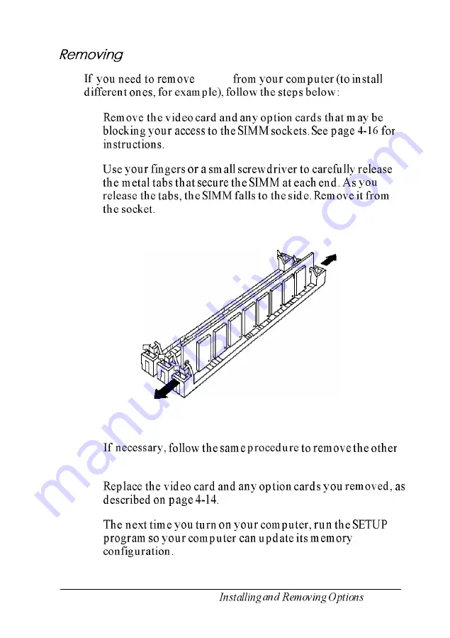
Страница 68: ...r a small screwdriver to carefully release the metal tabs that secure the SIMM at each end As you release the tabs the SIMM falls to the side Remove it from the socket 3 If necessary follow the same procedure to remove the other SIMMs 4 Replace the video card and any option cards you removed as described on page 4 14 5 The next time you turn on your computer run the SETUP program so your computer ...

Страница 69: ...ons 0 Although you can install an ISA option card in any of the four slots you can only install a VESA card in slot 2 or 3 Make sure you know what type of card you are installing 0 If you installed SIMMs the bottom slot slot 1 will accommodate only a half length card 0 In order to access the bottom slot you may have to remove the VGA adapter card and then reinstall it See page 4 16 for instruction...

Страница 70: ...nd set it aside Store it in a safe place in case you remove the option card later 3 Unpack the option card and adjust any switches or jumpers on it if necessary Check the option card instructions When you handle the card do not touch any of the components on the circuit board or the gold edged connectors If you need to set it down before you install it place it gently on top of its original packin...

Страница 71: ...s reach the slot push the card in firmly but carefully to insert it fully You should feel the card fit into place If it does not go in smoothly do not force it pull it all the way out and try again 5 Secure the end of the card to the computer with the retaining screw 4 16 Installing and Removing Options ...

Страница 72: ...ample You may also want to remove a card if you no longer need it Follow these steps 1 Remove the retaining screw securing the option card to the computer Then pull the card straight out of the slot 2 Set the card aside with the component side facing up When you are ready to re install the option card see page 4 14 for instructions Installing and Removing Options 4 1 7 ...

Страница 73: ...oard such as the disk drive connectors Follow these steps 1 Remove the video card and any option cards See the instructions above 2 Remove the retaining screw securing the bracket on the option card connector board to the power supply bracket 3 Pull the board straight up and out of its socket and set it aside 4 18 Installing and Removing Options ...

Страница 74: ...rom EPSON or buy the individual components separately Complete instructions for installing the processor are provided in the manual that comes with it Please follow those instructions carefully along with the following guidelines 0 Refer to the illustration on page 4 3 to locate the microprocessor socket on the system board You can install the new processor directly in this socket however you need...

Страница 75: ...ration you do not need to change any settings Replacing the Microprocessor Follow these steps to replace the microprocessor chip in your computer 1 Remove any video card or other option cards that may be blocking your access to the microprocessor socket See page 4 16 2 Use the illustration on page 4 3 to locate the microprocessor on the system board The microprocessor chip is inserted in a ZIF Zer...

Страница 76: ... open the ZIF socket 4 Gently pull the processor chip straight up and set it aside 5 Remove the replacement chip from its package and inspect the pins If they are bent do not install the processor chip Contact your vendor for a replacement 6 Position the processor chip over the ZIF socket aligning the notched edge of the chip marked with a dot with pin 1 on the socket A notch drawn on the system b...

Страница 77: ...t install a heat sink on the chip Follow the instructions that came with the heat sink or processor 10 If you are upgrading from an SX based processor to a DX or Pentium based processor you need to change the jumper setting of Jl to position A You may also need to change DIP switch settings to match the speed of your new processor See the table on page 4 7 for more information 11 Replace your vide...

Страница 78: ...ront of the computer position the cover so the lip on its bottom edge slides under the guiderails along both sides of the computer case as shown in the following illustration 2 Lower the cover and slide it straight back over the computer until it cannot go any farther Installing and Removing Options 4 23 ...

Страница 79: ...an electrical outlet Post installation Procedures After you install or remove options such as memory modules or a new processor you must run SETUP to update the computer s configuration See Chapter 2 for instructions You may also need to add some commands to your configuration files See your operating system manual and the manual that came with your optional equipment for instructions 4 24 Install...

Страница 80: ...ustrated here you should be able to install it the same way Some of the steps in this chapter may not apply for your drive see the documentation that came with the drive for more information Your computer can hold up to three drives in two horizontal drive bays and one vertical drive bay The upper horizontal bay contains the diskette drive that came with your system If your system came with only o...

Страница 81: ...ate the drive bays on your system back You can remove the hard disk drive already installed in the vertical drive bay and install a new one You can also install an additional hard drive in the lower horizontal bay 5 2 Installing and Removing Drives ...

Страница 82: ... next in this chapter To Install a hard disk drive Install a diskette drive or other device in a horizontal drive bay Remove a diskette drive or other device from a horizontal drive bay Remove a hard disk drive from the vertical bay See Setting the Hard Disk Drive Jumpers on page 5 4 Page 5 16 Page 5 27 Page 5 14 After you install or remove your drive s replace the computer s cover as described on...

Страница 83: ...on which you ll install the operating system that the computer loads into its memory each time you turn it on You can run application programs and store data on both the master and slave drive but the operating system must be on the master drive If you install a hard disk drive in your computer be sure to check the drive s jumper settings before you install it See the documentation that came with ...

Страница 84: ...y 0 Installing the hard disk drive in the vertical drive bay 0 Connecting the cables Before you install a hard disk drive be sure to check the jumpers on the drive For instructions see page 5 4 Removing the Mounting Frames Your hard disk drive may have mounting frames attached to it as shown below You need to remove these frames before you can install the drive in the vertical bay Installing and R...

Страница 85: ... grounding plate attached to one of the mounting frames If so remove the screws securing them to the mounting frame as shown below and remove the guiderail and grounding plate 2 Then remove the two screws securing each mounting frame to the drive and remove the frames as shown below 5 6 Installing and Removing Drives ...

Страница 86: ...tach it to the mounting plate in the vertical drive bay Follow these steps 1 Remove the screw securing the mounting plate to the horizontal drive bays and set it aside Then slide the mounting plate in the direction of the arrow and lift it out Installing and Removing Drives 5 7 ...

Страница 87: ... the four holes in the plate with the four holes in the drive as shown below bracket connectors The bracket on the mounting plate should be on the opposite side of the connector end of the drive 3 Use the screws that came with the hard disk drive or with your computer to secure the mounting plate to the drive 5 8 Installing and Removing Drives ...

Страница 88: ...rive bays with the bracket over the top and the connectors face the back of the computer as shown below bracket connectors The two tabs at the bottom of the mounting plate should be just above the two slots in the computer case Installing and Removing Drives 5 9 ...

Страница 89: ......

Страница 90: ...ld be connected to the main system board Locate the free connector on the end of this cable If there is a hard disk drive in the lower horizontal bay the middle connector is attached to that drive 3 Notice the small tab in the middle of the cable connector align this tab with the notch in the hard disk drive connector as shown in the following illustration N o t e When the hard disk drive ribbon c...

Страница 91: ... all the pins in the hard disk drive connector then push in the connector Caution If you do not correctly align the holes with the pins you could severely damage your hard disk drive when you push in the cable connector 5 12 Installing and Removing Drives ...

Страница 92: ...ur drive requires a small power supply cable connector use the small connector 6 Position the power supply cable connector so that its notched corners line up with the notched corners of the power supply connector on the hard disk drive Make sure the holes fit over all the pins and then push in the connector firmly Caution If you do not align the cable connector correctly you could severely damage...

Страница 93: ... drive bay 1 Disconnect the hard disk drive ribbon cable and power supply cable from the back of the drive as shown below Grasp the cable connectors and pull them straight out from the connectors on the hard disk drive so you do not bend the pins do not pull on the cables 5 14 Installing and Removing Drives ...

Страница 94: ...ove the screws securing the mounting plate to the hard disk drive You can store the mounting plate and its screw or replace it in the computer and secure it with the screw 4 Wrap the hard disk drive in its original packing materials and store it along with the screws 5 If you removed your computer s only hard disk drive disconnect the hard disk drive ribbon cable from the main system board and sto...

Страница 95: ...the upper bay You ll find steps for the following procedures 0 Attaching the mounting frames to a hard disk drive if necessary 0 Installing the drive 0 Connecting the cables If you are installing your computer s first hard disk drive it is best to use the vertical drive bay as described on page 5 5 N o t e Before you install a hard disk drive be sure to check the jumpers on the drive For instructi...

Страница 96: ... 5 6 to remove the guiderail and grounding plate Then go to Installing the Drive on page 5 18 Attaching Mounting Frames to a Hard Disk To attach mounting frames to a hard disk drive follow these steps 1 Locate the two mounting frames and the screws that came with the drive 2 As shown below place a mounting frame on one side of the drive and align it so that the holes in the drive are approximately...

Страница 97: ...1 Locate the two metal guiderails and screws that came with the computer 2 Using the appropriate screw holes attach one guiderail to each side of the drive or each mounting frame if attached as shown below The bracket on the guiderail should be near the end of the drive opposite the connector mounting frames brackei guiderail 5 18 Installing and Removing Drives ...

Страница 98: ...ou are installing a 5 25 inch diskette drive hold it so that the diskette release latch is above the diskette slot If you are installing a 3 5 inch diskette drive or a 5 25 inch 3 5 inch dual drive hold it so that the diskette release button s are on the right and the drive light is on the left If you are installing a hard disk drive hold it so that the component side faces down and skip to step 7...

Страница 99: ...ide of the drive with the notches on each side of the drive bay and slide the drive into the bay as far as it will go as shown below Secure the guiderails to the computer case with the two retaining screws notch1 h guiderail 5 20 Installing and Removing Drives ...

Страница 100: ...he computer cover upside down and locate the faceplate Remove the screws securing the faceplate to the inside of the cover and remove the faceplate as shown in the following illustration Store the faceplate and screws in a safe place you may want to install it again later Then go to Connecting the Cables on page 5 22 Installing and Removing Drives 5 2 1 ...

Страница 101: ...supply cable The steps below describe how to connect these cables to the drive If you are installing a diskette drive follow step 1 and then skip to step 3 If you are installing a hard disk drive start with step 2 1 Locate the diskette drive ribbon cable One end of the cable is connected to the system board If you are installing a second diskette drive in the lower horizontal drive bay the other e...

Страница 102: ...y onto the drive connector and push it into place Be careful to align the connector correctly otherwise you could severely damage your drive when you push it in Go to step 3 2 Locate the hard disk drive ribbon cable If you are installing a second hard disk drive one end of the cable is connected to the system board and the other end is connected to the first hard disk drive in the vertical drive b...

Страница 103: ...e connector align this tab with the notch in the hard disk drive connector as shown below notch power supply socket red wire tab When the hard disk drive ribbon cable is positioned correctly the red wire on the cable is aligned with pin 1 on the drive connector To identify pin 1 look for a 1 or 2 near the connector on the drive s circuit board Make sure the holes in the cable connector fit over al...

Страница 104: ...he power supply cables that lead from the power supply behind the horizontal drive bays The power supply cables may be secured in a plastic band on the side of the power supply If so unfasten the band to access the cables you can use any one that is free If your drive requires a small power supply connector use the smaller one Installing and Removing Drives 5 25 ...

Страница 105: ...rive s power supply connector as shown below Make sure the holes fit over all the pins and then push in the connector diskette drive notched corners hard disk drive Caution If you do not align the cable connector correctly you could severely damage your drive when you push it in 5 26 Installing and Removing Drives ...

Страница 106: ...e instructions to remove the diskette drive from the upper bay Follow these steps to remove a drive from a horizontal bay 1 Disconnect the drive ribbon cable and power supply cable from the back of the drive as shown below Grasp the cable connectors and pull them straight out from the connectors on the drive so you do not bend the pins do not pull on the cables diskette drive Installing and Removi...

Страница 107: ...hard disk drive 2 Remove the two retaining screws securing the drive to the drive bay Then grasp the front of the drive and pull it completely out of the bay 5 28 Installing and Removing Drives ...

Страница 108: ...16 5 Wrap the drive in its original packing materials and store it in a safe place 6 If you removed your computer s only hard disk drive disconnect the hard disk drive ribbon cable from the system board and store it as well If you removed one hard disk drive and are leaving another one in the computer you need to set the jumpers on the remaining drive to indicate that you now have only one hard di...

Страница 109: ...are leaving the bay empty or installing a hard disk drive in it you need to replace the front panel faceplate on the computer s cover Secure the faceplate to the inside of the computer s cover with the two screws as shown below 5 30 Installing and Removing Drives ...

Страница 110: ...e system board 1 Locate the hard disk drive connector on the system board As shown below it is next to the diskette drive connector between the option card connector board and the power supply The diskette drive ribbon cable is removed from the illustration for clarity option card connector board Installing and Removing Drives 5 3 1 ...

Страница 111: ...r on the end of the longest part of the cable the main system board connector Notice the small tab in the middle of the cable connector as shown in the illustration above Position the connector so that the tab aligns with the notch as shown below The option card connector board and diskette drive ribbon cable are removed from the illustration for clarity 5 32 Installing and Removing Drives ...

Страница 112: ...nfigure your computer for your new set of drives See Chapter 2 for instructions 2 If you installed a non IDE hard disk drive which requires a separate controller card to control it you need to run the SETUP program to disable the built in IDE hard disk drive interface 3 You may need to format the drive before you can use it All EPSON supplied drives are sold already formatted Check the manual that...

Страница 113: ...to be able to load your operating system from a new hard disk drive you need to install it on the drive See the documentation that came with your operating system for instructions 5 34 Installing and Removing Drives ...

Страница 114: ...vide the serial number of your computer its system BIOS version number its configuration including the type of disk drives monitor and option cards and the names and version numbers of any software programs you are using Use these guidelines to locate information about your system Serial number Look on the back panel of the computer to find the serial number System BIOS version System configuratio...

Страница 115: ...YS and press Enter to see a listing of your CONFIG SYS file This file contains your system configuration information At the MS DOS prompt type TYPE A U T O E X E C B A T and press Enter to see a listing of your AUTOEXEC BAT file This file contains your system startup information Error Messages Your computer s built in memory ROM contains a series of diagnostics programs called power on diagnostics...

Страница 116: ...wing table lists error messages that may appear during power on diagnostics If you receive an error message look it up in the table below it directs you to the proper troubleshooting section in this chapter or offers a solution If you do not see an error message read the section that covers your problem Power on diagnostics error messages Error message Action CMOS BATTERY HAS The CMOS battery is b...

Страница 117: ...SINCE LAST BOOT The display adapter has been changed Run SETUP See Chapter 2 FLOPPY DISK The system was unable to detect a diskette drive CONTROLLER ERROR controller OR NO CONTROLLER If you have no diskette drive run SETUP and select PRESENT none for both diskette drives If you have at least one diskette drive see Diskette Drive Problems FLOPPY DISK TYPE IS The installed diskette drive does not ma...

Страница 118: ...d see Diskette Problems PASSWORD CHECK You ve entered an incorrect password See FAILED SYSTEM Password Problems HALTED UNABLE TO INITIALIZE Your hard disk drive cannot be initialized See HARD DRIVE DRIVE Hard Disk Problems TYPE UNABLE TO Your drive is probably damaged Contact the RECALIBRATE HARD EPSON Connection DRIVE UNABLE TO RESET Your system cannot find or initialize your hard disk HARD DRIVE...

Страница 119: ... 2 If the power light still does not come on check the electrical outlet for power Turn off your computer unplug the power cord and plug a lamp into the outlet Turn it on to see if the outlet supplies power 3 If you installed or removed any of your system components such as a disk drive check to make sure you have reconnected all the internal and external cables correctly See Chapters 4 and 5 for ...

Страница 120: ...hanged If the computer does not display the operating system prompt after five minutes turn it off wait 20 seconds and try again If that doesn t work turn off the computer insert your main operating system diskette in drive A and turn on the computer If it still does not boot contact your sales representative or the EPSON Connection for assistance 3 Did you enter the correct password See Password ...

Страница 121: ...rature and correct the condition check for the following Room temperature above 90 F 32 C If this is the case relocate the computer to a cooler area A blocked power supply fan Make sure there is space around the power supply fan vents in the back and sides of the computer case Remove the computer s cover and check both inside and outside the computer for blockage Make sure there is ample room arou...

Страница 122: ... you know the current password but you want to change or delete it see Chapter 2 for instructions 3 If you do not know the current password and you cannot access your computer or use the SETUP program see the next section Accessing Your System If you have forgotten your current password follow these steps 1 Turn off the computer 2 Disable the password function by setting DIP switch 4 to On See Cha...

Страница 123: ...PgDn until the Password State option is set to Not Installed then press Enter See Chapter 2 for more information 10 Save your settings as you exit SETUP The computer reboots If you disabled password security you do not see the password prompt and can access your computer immediately If you set a new password you see the password prompt Keyboard Problems If you have trouble with the keyboard check ...

Страница 124: ...lay on the screen check that the monitor s power switch is on and that its power light is lit If the power light is on but you still do not see anything on the screen check the brightness and contrast controls 2 If the power switch is on but the power light is not turn off the monitor s power wait five seconds and turn it back on Wait to see if the screen displays any text 3 If the screen is still...

Страница 125: ...the monitor Diskette Problems If you see an error message or have trouble accessing data on a diskette try the following steps 1 You may have inserted the diskette upside down or it may not be inserted all the way Remove the diskette and reinsert it If the diskette drive has a latch be sure to turn it down to secure the diskette See Chapter 3 for detailed instructions on inserting and removing dis...

Страница 126: ...ng MS DOS error messages Disk Drive Error Abort Ignore Retry Disk error reading drive a Disk error writing drive a If you see one of these messages make sure the diskette is properly inserted in the drive If the problem persists try removing the diskette and reinserting it If the error message still occurs you may have a defective diskette Try copying the files from the bad diskette to a new diske...

Страница 127: ...efully follow all the steps in Chapter 5 Review the instructions and check all the cable connections to make sure you installed the drive correctly 3 Did you run the SETUP program and configure the correct type of diskette drive for your system See Chapter 2 for instructions 4 If the diskette drive is making loud or unusual noises do not attempt any further examination of it Contact the EPSON Conn...

Страница 128: ... be sure you run SETUP to update your configuration Check to make sure you selected the correct drive type and that you enabled the on board IDE hard disk drive controller with the Peripherals setup option in SETUP If you connected the IDE drive to a controller on an option card be sure you set the on board IDE controller to Disabled See Chapter 2 for instructions 4 If you installed a non IDE hard...

Страница 129: ...or performing these procedures are provided in your MS DOS manuals If you are using another operating system follow the instructions that came with it If you do not prepare the drive correctly you cannot store data on the disk For example if you partition the drive and format it for MS DOS or for another operating system but you do not copy the operating system to the drive you will not be able to...

Страница 130: ...ors the disk may have a physical problem Contact your sales representative or the EPSON Connection for assistance Software Problems If you have trouble with an application program try the following 1 If the application program does not start check that you are following the correct procedure for starting the program and that it is installed correctly If the program is stored in a directory on your...

Страница 131: ...Chapter 3 5 If resetting the computer does not help remove any diskettes turn off your system wait 20 seconds and turn it back on Then restart your application program If none of these solutions solve your software problem contact the software manufacturer for technical support Printer Problems Below are some general steps to follow if you have difficulty with your printer If the problem persists ...

Страница 132: ...s installed See your application program manual for instructions Also see your printer manual for additional instructions on using your printer with application programs 5 If your printer is properly set up but is still not functioning test it from the MS DOS level When the screen displays the MS DOS command prompt such as C or A hold down Shift and press PrintScreen This should print the contents...

Страница 133: ...lot Check the installation procedure described in Chapter 4 and also see the instructions that came with the card 2 Did you set the necessary DIP switches or jumpers on the option card See the card s manual for instructions 3 Did you set the necessary jumpers on the main system board See Chapter 4 for more information 4 Did you run the SETUP program to update your computer s configuration after in...

Страница 134: ...rial mouse did you disable the built in mouse port with SETUP and enable the correct serial port See Chapter 2 for instructions Memory Module Problems If you added extra memory to your system by installing SIMMs and that memory is not operating properly check the following 1 If the memory count displayed by the power on diagnostics program is incorrect you may not have installed the SIMMs correctl...

Страница 135: ... diagnostics program is incorrect the cache may have been installed incorrectly by the factory or your Authorized EPSON Servicer Call your sales representative or servicer to describe the problem 2 Were jumpers J4 through J7 set to indicate the new amount of cache Check the jumpers to see if they are set correctly See Changing the Jumper and DIP Switch Settings in Chapter 4 for instructions 3 If y...

Страница 136: ...Appendix A Specifications CPU and Memory Specifications A 1 ...

Страница 137: ...Controllers Interfaces A 2 Specifications ...

Страница 138: ...Mass Storage Input Devices Physical Characteristics Specifications A 3 ...

Страница 139: ...Power Supply Environmental Requirements A 4 Specifications ...

Страница 140: ...Power Source Requirements 120 Volt power source requirements Specifications A 5 ...

Страница 141: ...elease 3 2 version 4 2 SC0 Open Desk top 3 0 Microsoft Windows 3 1 Microsoft Windows for WorkGroups 3 11 Microsoft Windows NT 3 1 Certified as a workstation and a file server Your system has also been Novell tested and approved Options Available from EPSON Many options for enhancing and supplementing this product are available from EPSON including the following Monitors Keyboards Mass storage devi...

Страница 142: ...Serial and Parallel Port Connector Pin Assignments Specifications A 7 ...

Страница 143: ...DMA Assignments A 8 Specifications ...

Страница 144: ...Hardware Interrupts Specifications A 9 ...

Страница 145: ...System Memory Map A 10 Specifications ...

Страница 146: ...System l O Address Map Specifications A 1 1 ...

Страница 147: ...System I O address map continued A 12 Specifications ...

Страница 148: ... data is transmitted by varying the voltage levels in a continuous current and can produce an infinite number of colors or gray shades Application program A software program that performs a specific task such as word processing Note that an application program is different from an operating system which controls the computer s hardware and software Asynchronous Data transmission in which one machi...

Страница 149: ...on BAT When you type the filename the operating system sequentially executes the commands in that file BIOS Basic Input Output System Routines in ROM Read Only Memory that handle the transfer of information among various hardware components and between the hardware and your operating system Boot The process a computer performs to check its components and then load the operating system into memory ...

Страница 150: ...buffer that stores frequently used data where your microprocessor can access it faster Your computer s external cache is expandable to 256KB CGA Color Graphics Adapter A display adapter card that can generate up to 25 lines of text with 80 characters on each line two color graphics at 640 x 200 resolution or four color graphics at 320 x 200 resolution Chip A piece of silicon containing miniature t...

Страница 151: ... command prompt may look like this c Configuration The setup of your computer s internal and external components A typical configuration consists of a computer with a certain amount of memory one diskette drive and one hard disk drive connected to a monitor printer and keyboard Conventional memory The memory in the computer below 1MB that is available to MS DOS and application programs usually 640...

Страница 152: ...en you don t specify an alternative A default value stays in effect unless you override it temporarily or change the default value itself Device A piece of equipment that is part of a computer system such as a disk drive a monitor or a printer Device driver A file containing instructions that allow your computer to recognize and communicate with a device The device may be a printer monitor or othe...

Страница 153: ...S DOS and Operating system Double density A type of diskette format that allows you to store twice as much data as the previously used single density format A 3 5 inch double density diskette can store 72OKB of data A 5 25 inch double density diskette can store 360KB of data EGA Enhanced Graphics Adapter A display adapter card that allows you to display high resolution graphics on an EGA monitor I...

Страница 154: ...tracks and sectors and creates addressable locations where your operating system can find the data Heat sink A device used on some microprocessors to absorb and dissipate heat High density A type of diskette format that allows you to store more data than on single or double density diskettes A 5 25 inch high density diskette can store 1 2MB of data A 3 5 inch high density diskette can store 1 44MB...

Страница 155: ...d Jumpers alter the operation of a particular function Key disk A diskette containing a copy protected program that must remain in a diskette drive while you use the program See also Copy protected program Kilobyte KB A unit used to measure storage space in a computer s memory or on a disk One kilobyte equals 1024 bytes LIM EMS 4 0 Version 4 0 of the Lotus Intel Microsoft Expanded Memory Specifica...

Страница 156: ...nctions faster by using floating point numbers instead of whole numbers Megabyte MB A unit used to measure storage space in a computer s memory or on a disk One megabyte equals 1024KB kilobytes Megahertz MHz A unit used to measure oscillation frequency such as that of a computer s internal clock A megahertz is one million cycles per second Memory The area where your computer stores data Memory con...

Страница 157: ...EModulator A device that allows a computer to transfer data to and from another computer by transmitting signals over telephone lines Monochrome monitor A monitor that displays in only one color such as green white or amber Mouse A hand held pointing device with one or more buttons Sliding the mouse over a surface moves the cursor in the same direction on the screen Pressing or clicking a mouse bu...

Страница 158: ...system such as MS DOS OS 2 or UNIX provides the foundation for the other programs and controls hardware resources Option card A circuit board you can install inside the computer to provide additional capabilities such as a modem or an additional I O port Option cards plug directly into option slots so you do not have to alter a computer s circuitry to enhance your system OS 2 Operating System 2 Th...

Страница 159: ...a peripheral device Power on diagnostics Tests stored in a computer s ROM that the computer runs to check its internal circuitry peripheral device configuration and operating status each time you turn it on or reset it Processor speed See Operating speed Prompt A message displayed to request information or tell you what action to perform next See also Command prompt RAM Random Access Memory The ar...

Страница 160: ...e computer that keeps track of the time and date even when the computer is turned off by using power from a backup battery Refresh rate The frequency with which a monitor can redraw a screen image The faster the refresh rate the less the screen will flicker Reset To restart a computer without turning it off You can reset your computer by pressing Ctrl Alt Delete Resetting erases all data stored in...

Страница 161: ...a from a serial interface to a serial device over a single wire See also Interface and Parallel Shadow RAM The feature in your computer that copies the contents of the system video and external BIOS ROMs into the RAM area of memory to speed up processing SIMM See Memory module Subdirectory In a hierarchical disk directory structure a group of files in a directory within another directory or the ro...

Страница 162: ...s set for a common hardware and software interface to super VGA video adapters and other high performance local bus devices VESA or VL Bus interfaces support 32 bit data transfer at speeds of up to 33 MHz allowing your computer to process 20 times more data per second than an ISA bus VGA Video Graphics Array A high resolution display adapter that provides a variety of video modes Video card See Di...

Страница 163: ...tte or by placing a write protect tab over the notch on a 5 25 inch diskette You cannot change data on a write protected diskette ZIF socket Zero Insertion Force socket The type of socket on your system board that holds the microprocessor With this type of socket it is easy to remove and install processor chips 16 Glossary ...

Страница 164: ...rive Intro 4 2 5 5 l A 3 CGA adapter 2 9 4 14 CHKDSK command 6 14 Clock calendar A l CMOS battery 6 3 A l CMOS RAM 2 2 COM ports 2 12 Command stopping 3 6 6 18 Configuration files 6 2 system 1 10 2 l 6 l Connecting diskette drive cable 5 22 23 5 25 26 hard disk drive cable 5 l1 13 5 23 24 5 26 keyboard l 6 monitor l 4 mouse l 6 option card 4 14 parallel device l 5 power cord l 7 power supply cable...

Страница 165: ... 6 4 6 13 faceplate 5 21 5 30 inserting diskettes in 3 5 6 12 installing 5 16 locating 5 2 post installation 5 33 problems 6 12 6 14 Diskette drive continued release button 3 5 removing diskettes from 3 5 seek test SETUP 2 l1 SETUP option 2 5 specifications A 3 Diskette s error messages 6 13 formatting 6 13 inserting 3 5 6 12 key 3 9 problems 6 12 removing 3 5 write protecting 6 13 DMA assignments...

Страница 166: ...s 5 4 6 15 local bus IDE drivers Intro 2 2 l8 3 11 local bus interface Intro l 2 A 2 Hard disk drive continued locating 5 2 master 5 4 mounting frames 5 5 6 5 17 mounting plate 5 7 10 5 15 partitioning 6 15 16 post installation 5 33 preparing for use 5 33 6 16 primary 5 4 problems 6 14 17 removing from computer 5 14 5 16 5 27 30 secondary 5 4 SETUP options 2 5 8 2 13 slave 5 4 types 2 5 2 7 8 vert...

Страница 167: ...commands 3 9 test 2 13 Lighting for computer 3 3 Lights indicator hard drive access l 10 power SPEED l 9 3 9 6 6 Local bus controller 2 18 A 2 IDE drivers Intro 2 2 l8 3 11 IDE interface Intro 2 A 2 option slots Intro 2 A 2 video Intro l A 2 Lock keyboard 2 15 3 8 LPT ports 2 12 M Main system board components 4 3 DIP switches 4 6 7 4 9 drive cable connectors 5 31 help SETUP 2 16 jumpers 4 6 8 spec...

Страница 168: ...ntro 3 2 3 NumLock setting 2 13 6 11 A 3 0 Operating environments A 6 Operating system configuring 4 24 formatting hard disk for 6 16 installing l 10 2 18 reloading 3 7 version number 6 2 Option card connector board locating 4 3 removing 4 17 replacing 4 19 Option cards configuration 2 8 4 14 DIP switches 4 14 6 20 installing 4 14 ISA 4 14 jumpers 4 14 6 20 power limits 6 6 problems 6 4 6 6 6 12 6...

Страница 169: ...ecting l 5 DIP switches 6 19 parallel interface l 5 2 12 6 19 A 2 problems 6 18 serial interface l 5 2 12 6 19 A 2 Processor DIP switches 4 6 7 4 22 installing 4 19 22 jumper 4 6 7 4 20 4 22 locating 4 3 numeric Intro l Pentium class Intro 3 4 19 20 4 22 A l specifications A l upgrading Intro 3 Processor speed application programs 2 10 3 9 10 changing 2 10 3 9 DIP switches 4 6 7 keyboard commands ...

Страница 170: ...ting 4 3 problems 6 21 removing 4 13 SETUP 2 16 sockets 4 3 4 10 13 specifications 4 10 Slave drive 5 4 Slow processor speed 2 10 3 9 10 Socket s microprocessor 4 20 SIMM 4 3 4 10 13 ZIF 4 20 22 Software see Application programs Speaker A 2 Specifications A 1 12 Speed see Processor speed SPEED light l 9 3 9 Starting computer l 8 6 6 7 Static electricity l 2 Stopping a command or program 3 6 6 18 S...

Страница 171: ...2 2 18 display adapter Intro 2 1 4 2 8 9 A 2 interface A 2 port l 4 2 8 9 A 2 utilities Intro 2 VGA PGA EGA 2 8 9 Video BIOS ROM Intro l 2 12 A 10 Video cards configuring 2 8 9 DIP switches 4 6 7 4 15 display adapter Intro 2 1 4 2 S 9 A 2 installing 4 14 16 jumpers 4 15 problems 4 14 6 4 removing 4 16 VESA local bus Intro l 2 4 14 A 2 Video controller A 2 Video monitor see Monitor VI Bus Intro l 2...

Страница 172: ...5 265 0092 Fax 305 265 0097 Epson Argentina S A Buenos Aires Argentina Tel 541 322 7487 Fax 541 322 4637 Epson Chile S A Santiago Chile Tel 562 232 8966 Fax 562 233 3197 Epson Costa Rica S A San Jose Costa Rica Tel 506 34 6666 Fax 506 25 5709 Epson Mexico S A De C V Mexico D F Mexico Tel 525 395 9897 Fax 525 395 9499 Epson Do Brasil São Paulo SP Brazil Tel 5511 813 3044 Fax 5511 210 9290 Epson Ven...

Страница 173: ...132 Epson Hong Kong Ltd 25 F Harbour Centre 25 Harbour Road Wanchai Hong Kong Phone 831 4600 Fax 572 5792 Telex 65542 EPSCO HX Epson Australia Pty Ltd 17 Rodborough Road Frenchs Forest N S W 2086 Australia Phone 2 452 0666 Fax 2 451 0251 Telex 71 75052 Epson Electronics Trading Ltd Taiwan Branch l OF No 287 Nanking E Road Sec 3 Taipei Taiwan R O C Phone 886 2 717 7360 Free phone 886 080 211172 Fax...

Страница 174: ...0234 Fax 595 61 60566 Control De Procesos Informaticos Lima Peru Tel 5114 328 384 Fax 5114 355 017 Interfase S A Montevideo Uruguay Tel 598 249 4600 Fax 598 249 3040 Siser Ltda La Paz Bolivia Tel 591 2 34 32 45 Fax 591 2 35 92 68 McSilver S A Bogota Colombia Tel 571 230 1014 Fax 571 230 9205 C I L D S E Quito Ecuador Tel 593 2 54 3418 Fax 593 2 55 4780 A J Vierci CIA Asuncion Paraguay Tel 595 21 4...

Страница 175: ...De Computacion S A Guatemala Guatemala Tel 502 2 31 11 70 Fax 502 2 32 52 22 Micro Tee Managua Nicaragua Tel 505 2 66 27 15 Fax 505 2 66 27 58 Da Costas Limited Bridgetown Barbados Tel 809 427 5854 Fax 809 436 9870 The Computer Center Nassau Bahamas Tel 809 328 0304 Fax 809 328 0307 Compusupplies Ltd Kingston Jamaica Tel 809 925 8382 Fax 809 925 8115 Boolchand Pessomal N V Curacao Netherlands Anti...

Отзывы: