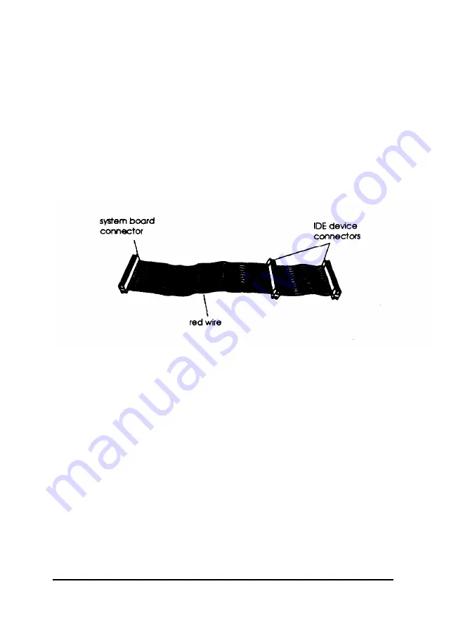
Connecting the Cables to the Front Internal Drive
Follow these steps to
connect
the IDE device and power cables
to the front internal drive:
1.
2.
3.
Locate the IDE device cables that are connected to the IDE
interface on the system board. They are flat cables with a
system board connector at one end and two IDE device
connectors at the other end. The cable has a red wire on
one side. (If necessary, see “Locating System Board
Components” in Chapter 4 to find the primary and
secondary IDE interfaces on the system board.)
Use the primary IDE interface for your boot drive and your
second hard disk drive; use the secondary IDE interface to
connect IDE CD-ROM drives, other IDE devices, or your
third and fourth drives. You cannot connect a CD-ROM
drive and hard disk drive to the same interface.
Identify the IDE device connector you will use on the IDE
device cable.
Locate pin 1 on the drive connector. The number 1 or 2 may
be printed on the drive’s connector or circuit board to
identify the side of the connector containing pin 1.
6-6
Installing and Removing Tower Drives
Содержание Endeavor 486I
Страница 1: ...EPSON User s Guide ...
Страница 5: ......
Страница 70: ...Installing and Removing Options 4 7 ...
Страница 73: ...CPU type jumper settings CPU type Intel or AMD Intel Cyrix UMC Jumper 4 10 Installing and Removing Options ...
Страница 78: ...SIMM configurations continued Installing and Removing Options 4 15 ...
Страница 170: ...Video Resolutions and Colors N o n i n t e r l a c e d a n d i n t e r l a c e d I n t e r l a c e d A S Specifications ...
Страница 173: ...IDE hard disk drive jumper settings DMA Assignments Specifications A 11 ...
Страница 174: ...Hardware Interrupts System Memory Map A 12 Specifications ...
Страница 176: ...Connector Pin Assignments Parallel port connector pin assignments J6 Active low logic A 14 Specifications ...
Страница 178: ...Options Available From EPSON Many options for enhancing and supplementing this product A 16 Specifications ...


