


DIP
switch
1
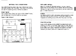
Jumper settings
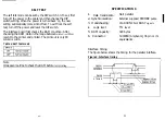
The table below contains information on switch functions, and
the factory setting of each switch. The switches on DIP switch
1 allow you to change interface functions.
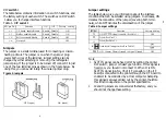
Table 1. DIP
switch 1
SW pin No.1
Function
ON Off Factory setting
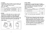
The tables below give you information about the interface
conditions that can be selected using jumpers. In all cases, ON
denotes the connection of the jumper (covering both termi-
nals), while OFF denotes the disconnection of the jumper.
I
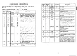
Table 2. Jumper settings
Jumper
Function
Factory Setting
J1
ON: SLCT IN signal is enable. (See Note 1.)
OFF
12
Fixed (See Note 2.)
-
J3
Fixed (See Note 2.)
-
1 - 1
I/F board enable/disable
Enable Disable
ON
1-2
Buffer enable/disable
Enable Disable
ON
1-3
Self test enable/disable
Enable Disable
OFF
I
I
1 - 4
Not used.
-
-
OFF
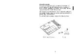
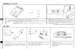
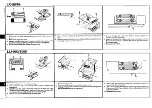
Jumpers
The jumper is a small terminal used for connecting or discon-
necting a circuit. The jumper is on when the jumper plug
covers both wires of the terminal. Jumper settings can be
changed by either attaching or removing the rectangular
jumper plug. If the jumper is to be turned off, connect it to just
one of the two terminal pins as shown in the figure below. By
doing this, you can avoid losing the unused jumper plug.
Figure 2. lumpers
OFF (open)
ON (close)
A
H
B
Data latch liming
selection.
See Table 3.
JG 1
ON: Connect Chassis Ground to Signal Ground.
OFF
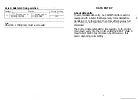
Note
1. SLCT IN signal can be fixed LOW by setting the printer
2.
DIP switch , jumper or SelecType function. If this signal is
fixed Low, you should not connect J1. When J1 is ON,
SLCT IN signal (pin No. 36 of I/F connector on the I/F
board) is connected to the printer through the I/F board to
enable it to be controlled by a Host computer. Sampling
this signal is always carried out by the printer, therefore
this function depends on the printer specification.
J2 and J3 jumpers are connected at the factory, and you
should not change these setting.
6
Содержание C82303
Страница 18: ...L xda xiI Xii NOILV IWLSNI 3 ...
Страница 19: ...C 000T 008 iTI we 98 08 X1 ...