EPSON AcuLaser C4000/C4100/C3000
Revision F
Disassembly and Assembly
Disassembly Assembly Procedures
4-362
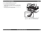
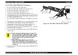
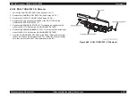
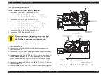
4.2.9.2 SENSOR ASSY ADC (PL6.1.11) Removal
1. Release the latch A of the printer body and open the CHUTE ASSY IN
(PL6.1.1).
2. Remove the BTR ASSY. (See Section 4.2.12.2.)
3. Lift the SENSOR ASSY ADC a little way from the CHUTE ASSY IN, and
disconnect the connector (P/J136).
4. Release the 4 hooks securing the SENSOR ASSY ADC to the CHUTE
ASSY IN of the printer body.
5. Remove the SENSOR ASSY ADC along with the SPRING ADC (PL6.1.12)
from the CHUTE ASSY IN.
6. Remove the SPRING ADC from the SENSOR ASSY ADC.
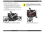
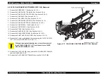
Figure 4-53. SENSOR ASSY ADC (PL6.1.11) Removal
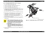
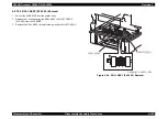
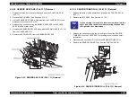
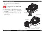
4.2.9.3 SENSOR TONER FULL (PL6.1.13) Removal
1. Release the latch A of the printer body and open the CHUTE ASSY IN
(PL6.1.1).
2. Remove the BTR ASSY. (See Section 4.2.12.2.)
3. Release the 2 hooks securing the left and right sides of the SENSOR
TONER FULL to the CHUTE ASSY IN by using a tool such as a small
screwdriver.
4. Disconnect the connector (P/J142) on the SENSOR TONER FULL.
5. Remove the SENSOR TONER FULL from the CHUTE ASSY IN.
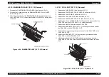
Figure 4-54. SENSOR TONER FULL (PL6.1.13) Removal
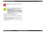
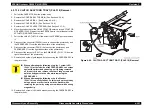
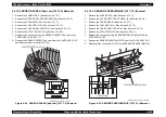
C H E C K
P O I N T
In the next step, it may help to insert a screwdriver into the
upper part of the connector when removing the hook from
the right side. (See illustration.)
Содержание AcuLaser C3000 Series
Страница 1: ...EPSON AcuLaserC4000 AcuLaserC4100 AcuLaserC3000 Color Laser Page Printer SEPG01012 SERVICE MANUAL ...
Страница 20: ...C H A P T E R 1 PRODUCTDESCRIPTIONS ...
Страница 71: ...C H A P T E R 2 OPERATINGPRINCIPLES ...
Страница 118: ...C H A P T E R 3 TROUBLESHOOTING ...
Страница 318: ...C H A P T E R 4 DISASSEMBLYANDASSEMBLY ...
Страница 472: ...C H A P T E R 5 ADJUSTMENT ...
Страница 477: ...C H A P T E R 6 MAINTENANCE ...
Страница 491: ...C H A P T E R 7 AcuLaserC4100 ...
Страница 548: ......
Страница 549: ......
Страница 550: ......
Страница 551: ......
Страница 552: ......
Страница 553: ......
Страница 554: ......
Страница 555: ...C H A P T E R 8 AcuLaserC3000 ...
Страница 579: ...Model AcuLaser C3000 Board C569MAIN BOARD Sheet 1 of 5 Rev B ...
Страница 580: ...Model AcuLaser C3000 Board C569MAIN BOARD Sheet 2 of 5 Rev B ...
Страница 581: ...Model AcuLaser C3000 Board C569MAIN BOARD Sheet 3 of 5 Rev B ...
Страница 582: ...Model AcuLaser C3000 Board C569MAIN BOARD Sheet 4 of 5 Rev B ...
Страница 583: ...Model AcuLaser C3000 Board C569MAIN BOARD Sheet 5 of 5 Rev B ...
Страница 584: ...C H A P T E R 9 APPENDIX ...
Страница 617: ...EPSON AcuLaser C4000 C4100 C3000 Revision F Appendix Wiring Diagrams 9 602 Figure 9 6 P J Location 6 ...
Страница 644: ...EPSON AcuLaser C4000 C4100 C3000 Revision F Appendix Wiring Diagrams and Signal Information 9 629 ...
Страница 674: ......
Страница 675: ......
Страница 676: ......
Страница 677: ......
Страница 678: ......
Страница 679: ......
Страница 680: ......

