


REV.-A
4.3 ADJUSTMENT
DISASSEMBLY, ASSEMBLY, AND ADJUSTMENT
This section describes the adjustment procedures required for assembling the LQ-500/L-1000 printer. When
disassembly or replacement is performed during maintenance or repair of the parts described in this section,
perform the following adjustments to ensure proper operation.
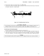
4.3.1 Platen Gap Adjustment
Adjust the gap between the platen and the printhead when the carriage guide shaft or carriage guide shaft
levers are rotated or removed, or the printing is abnormal.
1.
Remove the printer mechanism (refer to Section 4.2.4).
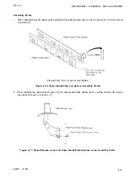
2.
Install the paper guide and the platen unit on the printer mechanism.
3.
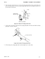
Remove the printhead, then remove the ribbon mask using tweezers. When removing the ribbon mask,
pull it frontward slightly, then lift it.
Figure 4-34. Removal of Ribbon Mask
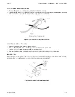
4. Reinstall the printhead.
5.
Set the head adjust lever at the position nearest the platen.
6.
Manually move the carriage to column 10.
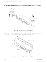
7.
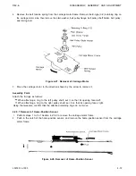
Insert a thickness gauge (0.45 mm) between the platen and the printhead, and adjust the left and right
carriage guide shaft levers so that the gap becomes 0.44 m 0.47 mm. When the weight of the thickness
gauge causes it to slip down, the gap adjustment is adequate.
When setting the position of the carriage guide shaft lever, be sure that both tabs A and B do not enter
the notch at the same time. It
IS
designed so that tab B may not enter when tab A is inside, and that tab
A may not enter when tab
B
is inside.
LQ-500/L-1000
4-23
Содержание ActionPrinter L-1000
Страница 1: ...LQ 500 L 1000 TECHNICAL MANUAL EPSON ...
Страница 3: ...REV A REVISION SHEET iv LQ 500 L 1000 ...
Страница 18: ...GENERAL DESCRIPTION REV A Figure 1 5 Character Matrix 1 10 LQ 500 L 1000 ...
Страница 39: ...PRINCIPLES OF OPERATION REV A 2 2 LQ 500 L 1000 Figure 2 1 Cable Connections ...
Страница 44: ......
Страница 47: ...PRINCIPLES OF OPERATION REV A Table 2 2 Power Supply Applications 2 10 LQ 500 L 1000 ...
Страница 64: ...REV A PRINCIPLES OF OPERATION Figure 2 30 Initialization Program Flowchart Cont LQ 500 L 1000 2 2 7 ...
Страница 65: ...PRINCIPLES OF OPERATION REV A Figure 2 30 Initialization Program Flowchart Cont 2 2 8 LQ 500I L 1000 ...
Страница 77: ...PRINCIPLES OF OPERATION 2 40 REV A Figure 2 40 Schmitt Trigger Circuit LQ 500 L 1000 ...
Страница 82: ...REV A PRINCIPLES OF OPERATION Table 2 14 Acceleration Time Data 1 2 Excitation LQ 500 L 1000 2 45 ...
Страница 83: ...PRINCIPLES OF OPERATION REV A Table 2 15 Deceleration Time Data 1 2 Excitation 2 46 LQ 500 L 1000 ...
Страница 100: ...REV A PRINCIPLES OF OPERATION Table 2 20 Control Commands LQ 500 L 1000 2 63 ...
Страница 106: ...REV A PRINCIPLES OF OPERATION Figure 2 64 Printing Routine LQ 500 L 1000 2 69 ...
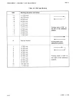
Страница 141: ...DISASSEMBLY ASSEMBLY AND ADJUSTMENT Table 4 5 VR2 Specifications REV A 4 26 LQ 500 L 1000 ...
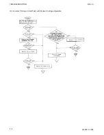
Страница 148: ...TROUBLESHOOTING REV A 1 Printer Does Not Operate with Power Switch ON 5 4 LQ 500 L 1000 ...
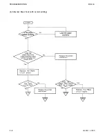
Страница 149: ...REV A TROUBLESHOOTING 2 Abnormal Operation of Carriage LQ 500 L 1000 5 5 ...
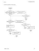
Страница 150: ...TROUBLESHOOTING REV A 3 Incorrect Printing in Self Test with Normal Carriage Operation 5 6 LQ 500 L 1000 ...
Страница 151: ...REV A TROUBLESHOOTING Figure 5 3 Printhead Resistance LQ 500 L 1000 5 7 ...
Страница 152: ...TROUBLESHOOTING REV A 4 Abnormal Paper Feed with normal printing 5 8 LQ 500 L 1000 ...
Страница 153: ...REV A TROUBLESHOOTING 5 Abnormal Operation of Control Panel LQ 500 L 1000 5 9 ...
Страница 156: ...TROUBLESHOOTING REV A Table 5 6 Power Supply Circuit Unit Repair 5 12 LQ 500 L 1000 ...
Страница 157: ...REV A T R O U B L E S H O O T I N G ...
Страница 162: ...REV A MAINTENANCE Figure 6 2 LQ 500 L 1000 Lubrication Points LQ 500 L 1000 6 3 ...
Страница 163: ......
Страница 168: ......
Страница 169: ...APPENDIX REV A Table A 2 µPD7810 Mode Setting Table A 4 µPD7810 PF Operation A 4 LQ 500 L 1000 ...
Страница 170: ...REV A APPENDIX Table A 5 µPD7810 7811 Port Functions LQ 500 L 1000 A 5 ...
Страница 173: ...APPENDIX REV A Figure A 7 E01A05KA Block Diagram A 8 LQ 500 L 1000 ...
Страница 174: ...REV A Table A 6 E01A05KA Pin Functions APPENDIX LQ 500 L 1000 A 9 ...
Страница 176: ...REV A APPENDIX Figure A 9 E05A02LA Block Diagram Table A 7 E05A02LA Pin Functions LQ 5001 L 1000 A 11 ...
Страница 185: ...APPENDIX REV A A 20 LQ 500 L 1000 ...
Страница 186: ...REV A Table A 8 CN2 Connector Table A 9 CN3 Connector Cont A P P E N D I X LQ 500 L 1000 A 21 ...
Страница 187: ...APPENDIX REV A Table A 10 CN4 Connector Cont Table A 12 CN6 Connector Cont A 22 LQ 500 L 1000 ...
Страница 188: ...REV A APPENDIX Table A 17 Part No Reference Table LQ 500 L 1000 ...
Страница 189: ...APPENDIX REV A Figure A 24 LQ 500 Exploded Diagram A 24 LQ 500 L 1000 ...
Страница 190: ...REV A APPENDIX Figure A 25 M5410 Printer Mechanism Exploded Diagram LQ 500 L 1000 A 25 ...
Страница 191: ...APPENDIX REV A Figure A 26 Tractor Unit A 26 LQ 500 L 1000 ...
Страница 192: ......


