


29
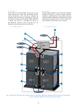
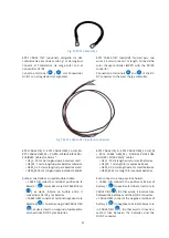
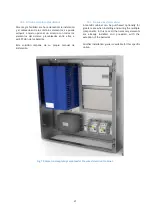
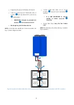
La conexión de este accesorio se realizará en serie
entre la conexión al variador (P+, N- y tierra) y el
convertidor tal y como se representa en la Fig. 21. El
filtro DC deberá colocarse lo más cerca posible del
variador. Es filtro DC irá marcado para indicar la
posición que queda en el lado del VVVF (variador de
frecuencia).
This item
’s
connection will be made in series between
the frequency controller connection (P+, N- and
ground) and the converter as shown in Fig. 21. The DC
filter should be placed as close as possible to the
frequency controller and it will be labelled to indicate
the correct position.
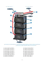
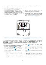
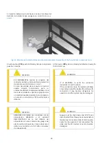
2.6.6.
Módulo interfaz CAN
Si se requiere comunicación CAN, hay un módulo
disponible para ello. Antes de la instalación, se debe
asegurar que el convertidor está desconectado, el
interruptor principal en posición OFF, los portafusibles
abiertos y el conector
desconectado. Los
siguientes pasos los debe llevar a cabo personal
cualificado:
-
Instalación
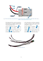
El conector de 8 vías de la imagen de la izquierda debe
ser conectado al conector
del EPC (solo acepta una
posición). Después de conectar el módulo, se debe
atornillar con un tornillo de métrica M3 en el agujero
especificado en la imagen inferior derecha.
2.6.6.
CAN interface module
If CAN communication is required, a CAN interface
module is available. Before the installation, make sure
that the EPC is disconnected, the main switch should
be switched off, the fuse holders opened and
connector disconnected. The following steps should
be carried out by qualified personnel:
-
Installation
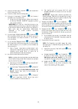
The 8-way connector in the left hand picture shown
below should be connected to connector
of the
EPC (only one position is possible). After connecting
the module, it should be attached using a M3 screw in
the hole in the right hand picture below.
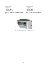
Fig. 22 Conexionado módulo CAN al convertidor/ CAN module connection to DC/DC converter.
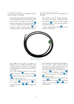
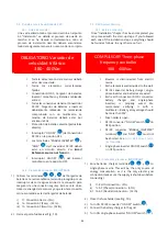
-
Cableado
El módulo CAN ya está preparado para iniciar la
comunicación, aunque es necesario mencionar que el
conector
de la izquierda de la imagen inferior está
reservado y el de la derecha
es el que debe usarse
para la comunicación.
CONECTOR 7. CAN 1
-
7A) GND
-
7B) CAN Low
-
7C) CAN High
-
7D) Salida 5V 0.1A
-
Wiring
Now, the module is ready for CAN communication. It
is necessary to mention that the connector
on
the left is reserved and the one on the right
is
free for communication.
CONNECTOR 7. CAN 1
-
7A) GND
-
7B) CAN Low
-
7C) CAN High
-
7D) 5V 0.1A Out
6
5
6
5
8
7
8
7
Содержание P2S Series
Страница 1: ...1 Manual de instalaci n Installation guide P2S Series plug single phase P2S powered by...
Страница 2: ...2 Versi n 4 6 June 2018 Epic Power Converters S L...
Страница 9: ...9 Fig 3 Convertidor DC DC 5k5 5k5 DC DC Converter 0 1 2 3 4 6 10 9 7 8 5...
Страница 55: ...55 Dimensiones EPCL 5K5 EPCL 5k5 dimensions...
Страница 56: ...56 6 6 Dimensiones del cargador de bater as 6 6 Battery charger dimensions...
Страница 57: ...57 6 7 Dimensiones del inversor monof sico 6 7 Single phase inverter dimensions Inversor TS 400 TS 400 Inverter...
Страница 58: ...58 Inversor TS 700 TS 700 Inverter...
Страница 59: ...59 6 8 Dimensiones del Controlador de carga solar 6 8 Solar charge controller dimensions...
Страница 61: ...61 6 9 2 Bastidor bater as Small 4x1 6 9 2 Small batteries rack 4x1...
Страница 62: ...62 6 9 3 Bastidor bater as Medium 6 9 3 Medium batteries rack...