

How to Use This Guide
Use
this
guide
to
set
up
your
Enterasys
®
G
‐
Series
switch
(pictured
below)
and
optional
components.
For
complete
instructions,
see
the
Enterasys
G
‐
Series
Hardware
Installation
Guide
.
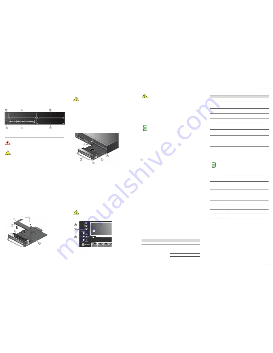
Figure 1 G-Series Ethernet Switch (G3G124-24 Displayed)
Handling the G3 Switch and Components
Unpacking the Switch or Components
Unpack
the
switch
as
follows:
1. Remove
the
packing
material
protecting
the
switch.
2. Remove
the
switch
or
component
from
the
non
‐
conductive
bag.
3. Perform
a
visual
inspection
of
the
switch
for
any
signs
of
physical
damage.
Contact
Enterasys
Networks
if
there
are
any
signs
of
damage.
See
“Getting
Help”
for
more
information.
Installing the Optional PoE module into an IOM Card
If
you
have
purchased
an
optional
PoE
module
(G3G
‐
POE),
you
can
install
it
before
installing
the
G3G
‐
24TX
IOM
card
into
the
G
‐
Series
base
system
chassis
or
at
any
time
by
first
removing
the
IOM
card
as
described
in
“Removing
an
IOM
Card”
.
To
install
the
PoE
module
in
an
IOM
card:
1. Gently
plug
the
PoE
module
into
the
IOM
card
by
fitting
the
standoffs
into
the
PoE
board
mounting
holes
as
shown
in
Figure 2
.
There
should
be
a
direct
vertical
translation
of
standoffs
to
PoE
mounting
holes.
2. Using
the
screws
shipped
with
the
PoE
module,
firmly
attach
the
PoE
module
to
the
IOM
card.
Figure 2 Installing a PoE Module in the G3G-24TX
1
USB Console Port
4
Optional IOM Card Slot 2
2
Optional IOM Card Slot 3
5
Fixed Switch Ports
3
Optional IOM Card Slot 4
6
RJ45 Console Port
Electrical Hazard:
Only qualified personnel should perform
installation procedures.
Caution:
The switch can be damaged by electrostatic discharge.
Attach an ESD wrist strap before handling the switch or
components.
1
Fastening screws
4
PoE Module’s IOM card connector
2
PoE daughter card module
5
G3G-24TX IOM card (motherboard)
3
IOM card’s PoE connector
Installing an IOM Card
To
install
an
IOM
card:
1. Loosen
the
captive
screws
on
the
coverplate
and
remove
the
coverplate
from
the
slot.
2. Insert
the
IOM
card
in
the
guide
rail
of
the
slot.
Gently
slide
the
card
into
the
slot,
as
shown
in
Figure 3
,
until
the
IOM
card
engages
the
connector
on
the
backplane
and
the
IOM
card
locks
into
place
and
is
flush
with
adjoining
coverplates.
3. Tighten
the
two
captive
screws.
Figure 3 Installing the IOM card (G3G-24TX with optional PoE shown)
4. If
installing
additional
modules,
wait
until
the
slot
status
LED
for
the
previously
installed
IOM
is
solid
green
before
installing
additional
modules.
Save
coverplates
for
optional
future
use.
5. After
completing
all
module
installation,
be
sure
to
install
coverplate(s)
over
any
unused
IOM
slot(s)
to
contain
EMI
radiation
and
ensure
proper
air
circulation.
Removing an IOM Card
1. Disconnect
any
cabling
from
the
IOM
card.
2. Loosen
the
IOM
card’s
two
captive
screws.
3. Press
the
power
off
button
corresponding
to
the
slot
from
which
you
want
to
remove
the
IOM
card
as
shown
in
Figure 4
.
Figure 4 Chassis LEDs
4. When
the
slot’s
POWER
OFF
status
LED
turns
amber,
gently
slide
the
module
out
of
the
slot.
Caution:
If you are installing multiple IOMs into a switch that is
running, wait until the previously installed IOM is completely
initialized before attempting to install the next IOM. Initialization is
complete when the slot’s status LED turns solid green.
1
IOM slot 2
4
Optional G3G-POE module
2
IOM handle
5
IOM
3
Captive screw
Caution:
Do not attempt to power-down and remove more than one
IOM at a time. You must complete the removal procedure outlined in
this section before attempting to remove another IOM.
1
Power Supply LEDs
3
IOM power off buttons (Slot 2, 3 and 4)
2
SYSTEM LED
4
IOM power off status LEDs (Slot 2, 3 and 4)
Replace
the
slot’s
coverplate
to
contain
EMI
radiation
and
ensure
proper
air
circulation.
Installing a Power Supply
These
power
supplies
can
be
installed
on
the
G
‐
Series
switch:
• G3
‐
PWR,
a
400
‐
watt
AC
power
supply
(requires
15A
circuit)
• G3
‐
PWR
‐
POE,
a
1200
‐
watt
AC
power
supply
(requires
20A
circuit)
To
install
a
single
power
supply
in
the
G
‐
Series
switch:
1. Holding
the
power
supply
by
its
handle,
position
it
with
the
status
LEDs
to
the
left
and
align
it
with
the
slot
opening.
2. Carefully
slide
the
module
until
it
connects
to
the
backplane.
If
significant
resistance
is
encountered
before
the
power
supply
is
seated,
remove
and
reinsert
it.
Do
not
force
the
module
into
place.
3. Secure
the
power
supply
to
the
chassis
by
tightening
the
captive
screws.
4. If
you
are
finished
installing
IOM
cards
and
are
ready
to
connect
to
a
power
source,
plug
the
power
cord
into
the
power
supply
AC
inlet,
then
into
a
grounded
outlet.
Completing the Setup and Downloading the Latest
Firmware
Once
you
have
connected
power
to
the
G3
switch
and
verified
LED
activity,
you
can
complete
the
setup
process.
For
more
information,
see
the
Enterasys
G
‐
Series
Hardware
Installation
Guide
.
1. Determine
the
latest
G3
firmware
version
at:
http://secure.enterasys.com/services/support/downloads/software
2. Connect
the
switch
to
the
network.
3. Connect
a
management
station
to
the
console
port.
4. Verify
that
the
network
devices
connected
to
the
switch
ports
are
powered
on,
and
that
each
link/activity
LED
is
on
(solid
green
or
blinking
green).
5. At
the
device
connected
to
the
console
port:
a. Enter
admin
for
Username.
b. At
the
Password
prompt,
press
ENTER
(RETURN).
c. At
the
command
prompt,
determine
if
the
latest
firmware
image
is
loaded
on
the
switch
by
entering
this
command:
show version
d. If
the
output
(under
FW
Version
)
displays
an
older
version
number
than
that
determined
in
Step
1,
download
and
activate
the
new
version
as
directed
on
the
download
website
or
use
the
CLI
commands
listed
in
Table 1
.)
Basic Setup Commands
Table 1
lists
CLI
commands
that
are
required
for
setting
up
the
G3
switch
with
the
latest
firmware.
Table 2
lists
additional
configuration
commands
for
your
G3
switch.
For
the
complete
list
of
CLI
commands,
see
the
Enterasys
G
‐
Series
CLI
Reference
.
Caution:
Use caution when removing an IOM on which you have an
optional PoE module installed to avoid damaging the PoE module.
Note:
The following procedure is for installing a single power supply.
For instructions on installing a second power supply, power supply
planning considerations, and advanced power configurations, see
the
G
‐
Series
Hardware
Installation
Guide
.
Table 1 Required CLI Setup Commands
Step Task
CLI commands
1
Set a new password
set password [
username
]
2
Set the switch IP address
set ip address
ip-address
[mask
ip-mask
] [gateway
ip-gateway
]
3
Download, activate, and
verify new firmware on the
switch using TFTP copy.
copy tftp://
tftp_svr_ip_addr
/
filename
system:image
set boot system
filename
show version
Specifications
For
a
complete
list
of
specifications,
see
the
Enterasys
G
‐
Series
Hardware
Installation
Guide
.
Interfaces
Switch Dimensions
Size:
8.8
H
x
44.1
W
x
48.1
D
(cm)
Power Supply Input Voltage
G3
‐
PWR:
100
to
240VAC/6A
G3
‐
PWR
‐
POE:
100
‐
125VAC/12A
to
200
‐
240VAC/7A
Temperature and Humidity
Operating:
0ºC
to
50ºC
Storage:
‐
40ºC
to
+70ºC
Operating
relative
humidity:
5%
to
95%
(non
‐
condensing)
Table 2 Optional CLI Setup Commands
Task
CLI commands
Save the active configuration
save config
Enable or disable SSH
set ssh enable | disable
Enable or disable Telnet
set telnet {enable | disable}
[inbound | outbound | all]
Enable or disable HTTP
management (WebView)
set webview {enable | disable}
Enable or disable SNMP port link
traps
set port trap
port-string
{enable | disable}
Set the per port broadcast limit
set port broadcast
port-string
threshold-value
Configure a VLAN
set vlan create
vlan-id
set port vlan
port-string
vlan-id
modify-egress
Set a Syslog server IP and severity
set logging server
index
ip-addr
ip-addr
severity
severity
state
enable
Configure and enable a RADIUS
server.
set radius server
index
ip-addr
port
[
secret-value
]{realm
{management-access | any |
network-access}
set radius enable
Note:
The 10BASE-T/100BASE-TX/1000BASE-T ports on the
G3G124-24Psupport 802.3af PoE connections out-of-box. The
10BASE-T/100BASE-TX/1000BASE-T ports on the G3G124-24
and G3G-24TX IOM card can support 802.3af PoE connections
by installing the optional G3G-POE module.
G3G124-24
• 24 10BASE-T/100BASE-TX/1000BASE-T ports
• Two combo 1000BASE-SX, 1000BASE-LX,
100BASE-FX, or 1000BASE-TX SFP ports
G3G124-24P
• 24 10BASE-T/100BASE-TX/1000BASE-T 802.3af PoE
ports
• Two combo 1000BASE-SX, 1000BASE-LX,
100BASE-FX, or 1000BASE-TX SFP ports
G3G170-24
• 24 1000BASE-SX, 1000BASE-LX, 100BASE-FX, or
1000BASE-TX SFP ports
G3G-24TX
• 24 10BASE-T/100BASE-TX/1000BASE-T ports
• Two combo 1000BASE-SX, 1000BASE-LX,
100BASE-FX, or 1000BASE-TX SFP ports
G3G-POE
• Add-on PoE module for G3G124-24 switch and
G3G-24TX IOM
G3G-24SFP
• 24 1000BASE-SX, 1000BASE-LX, 100BBASE-FX,
1000BASE-TX SFP ports
G3K-2XFP
• Two 10-Gigabit Small Form Factor Pluggable (XFP)
interfaces
G3K-4XFP
• Four 10-Gigabit Small Form Factor Pluggable (XFP)
interfaces


