Operation Instruction of BS Series Solar Pumping Inverter Installation and Wiring
22
Warning: risk of electric shock! Before shifting solar panel, disconnect pumping inverter AC
and DC. Besides, allow 5-minute internal capacitance discharging.
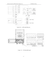
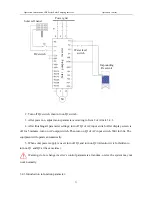
2.6 Introduction to the Wiring of Water Level Sensor
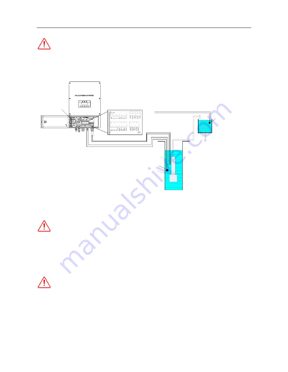
Figure 2-25 Wiring Diagram of Water Level Detector
Notice: connect water level sensor 1 and detect water shortage. Respectively connect two
signal lines of sensor with S4 and COM of I/O circuit board. When water level sensor 1 detects that
the water level of well is lower than the level set by sensor, the pumping inverter will delay for 60s,
then turn off output protection pump. The water level recovers. Wait for 600s, then the pumping
inverter re-works normally.
Notice: connect water level sensor 2 to defect whether water is full. Connect two signal
lines of sensor with S2 and COM. When water level sensor 2 detects that the water level of water
tank exceeds the level set by sensor, the pumping inverter delays for 60s and turns off output; when
water level is lower than set level, wait for 120s, then pumping inverter re-starts to work normally.
DC Switch
Connect S2 and COM
Connect Three-Phase Output
Connect S4 and COM
Water Level Sensor 2
Water Pump
Water Level Sensor 1
Water Well
Impounding Reservoir
Содержание BS-1100-L
Страница 1: ...Solar Pumping Inverter User s Manual...
Страница 41: ...Operation Instruction of BS Series Solar Pumping Inverter Operation Control 35...
Страница 47: ......

