DESCRIPTION & USE
INTRODUCTION
The LifeSpeed iQ
TM
range of chargers is designed to recharge
24 V, 36 V, 48 V, 72V or 80 V batteries with 3-phase mains
supply. The microprocessor-controlled unit automatically
recognises the battery (voltage, capacity, charge level, etc.)
and very effectively analyses its condition for optimum
handling. Several charging profiles are available (vented
lead/acid, NexSys
®
, gel or Water Less
®
/Water Less
®
20 batte-
ries) depending on the configuration selected by the user.
The capability for desulphation, equalisation and refresh
charging is also included.
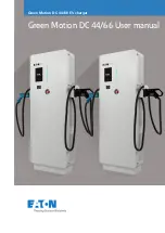
EXTERNAL COMPONENTS
Presented below:
Ref.
Function
1.
Control panel with LCD display
2.
USB port
3.
Navigation button
4.
Modules
5.
Input cable
6.
Connectors for options:
ethernet, electrovalve, Lifenetwork iQ
7.
Output cables
8.
Output cables
9.
Ventilation panels
10.
Dual harness-only 6 bay cabinet
11.
AC safety switch
Figure 1:
Principal components of the charger.
CONTROL PANEL
Incorporates LCD Display, USB port and navigation button.
LCD Display
The display is fitted with 5 different colours indicating the
status of the charger
Navigation button
Functions of the keys
The keys offer the following general functions:
Key
Function
Navigation in the menu.
Start/End of list (press 2 seconds)
The central button is equipped with
a
two-coloured
LED
Green/Red
(Green: charger is waiting
Red: charger is operating)
GREEN/RED
Stop or Start of charge
Selection of active menu or validation
of value stored
Cancel
the
value
stored
(press
2
seconds)
Start an equalisation charge.
Access to a sub-menu.
Access to the menus (press 3 seconds)
Close the window.
UNPACKING
The charger is delivered with the following:
•
2 m AC mains cable.
•
3 m DC battery cable.
•
This technical manual.
MECHANICAL INSTALLATION
The charger is intended to be wall mounted (only 3 bay cabi-
net) or floor standing and must be installed in the vertical
orientation. The distance between 2 adjacent chargers
should be at least 0.3 m.
See paragraph
Recommendations
and avoid areas where
the chargers may be splashed with water, or saline
environments.
ELECTRICAL CONNECTIONS
3-phase input
Connection to the mains supply is 400V AC 3-phase and must
be connected using a suitable plug and adequately sized cir-
cuit breaker (not included). Current requirements in Amps
are indicated on the charger information plate.
Battery output
It is essential to ensure correct polarity. However, reversed
polarity will result in blowing the output fuse, inability to
charge and the fault code
DF2
will be displayed.
See
Messages and fault codes.
Connection to the battery should be done using the cables
supplied:
•
RED cable: POSITIVE.
•
BLACK cable: NEGATIVE.
FACTORY SETUP
The charger is delivered with a factory setup as follows:
Profile
As ordered
Output DC cable length
3 m
Configuration
As ordered
Automatic equalisation
No
Delayed start enabled
No
1
2
3
5
4
6
7
8
9
6
FUNCTION
Waiting status until battery connected
Battery on charge
Alternating, on charge indicating a pump
defect, overdischarge, thermal fault or
module failure
Battery charged
Charger faults DF1, DF2, DF3, TH,
WRG MOD
Alternating, battery charged with pump
defect, overdischarge or module failure
COLOUR
Dark blue
Light blue
Light blue Orange
Green
Red
Green
Orange
10
11