
27
017-220-J0 Rev C
8. Theory of Operation
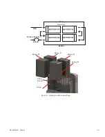
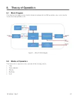
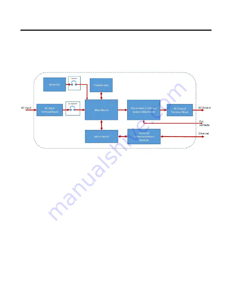
8.1 Block Diagram
The following block diagram shows the interconnection between the four PCB assemblies, input, output and the
transformer in the Alpha Micro 100.
Figure 9 — Micro 100 block diagram
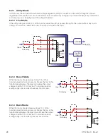
8.2 Modes of Operation
The following list of operation modes is explained in the following sections.
• Utility
• Backup (Inverter)
• Standby
• Shutdown
• Fault
Содержание Alpha Micro 100
Страница 1: ...Alpha Micro 100 UPS Technical Guide 017 220 J0 Effective 09 2020...
Страница 2: ......
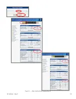
Страница 36: ...35 017 220 J0 Rev C Figure 14 Web Interface Bulk Charging Menus...
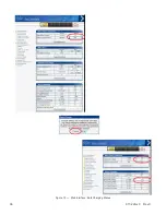
Страница 37: ...017 220 J0 Rev C 36 Figure 15 Web Interface Bulk Charging Menus...
Страница 85: ......
Страница 86: ......
Страница 87: ......