8
5.0 RECEIVING INSTRUCTIONS
Visually inspect all components for shipping damage.
Shipping damage is not covered by warranty. If shipping
damage is found, notify carrier at once. The carrier is
responsible for all repair and replacement costs resulting
from damage in shipment.
1
2
3
4
5
7
8
9
10
6
11
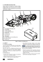
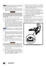
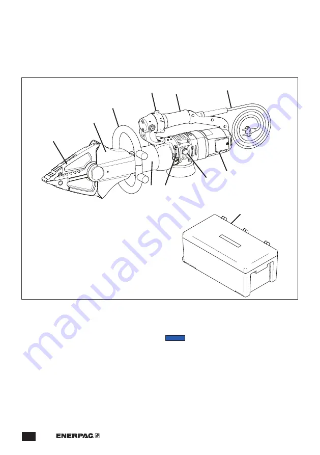
Figure 1, Features and Components
Key:
1. Cutting Blades/Spreading Jaws
2. Cutting Head
3. Positioning Handle
4. Control Knob (open/close)
5. Grip/Handle
6. AC Power Cord
7. Electric Motor
8. Oil Reservoir
9. Manual Release Lever (spreading only)
10. Hydraulic Cylinder
11. Storage Case
6.0 SET-UP
6.1 Delivery and Handling
The cutter and various related items are housed inside a
plastic storage case. The cutter should be stored in this
case when not in use.
Place the cutter on a substantial and stable work
surface. The work surface must be of sufficient capacity
to support the weight of the cutter plus the additional
weight of the material to be cut. Refer to Section 2.2 for
cutter weight.
6.2 Before Start-up
• Be sure that the shipment includes all components
and that there is no obvious damage.
• Read the following sections of this manual to become
familiar with cutter features and safety devices.
• Verify that the AC power supply is of the correct
specifications and capacity to power the cutter. Refer
to Section 7.0 of this manual for additional information.
NOTICE
Be sure that cutter jaws are open as far as
possible before removing oil reservoir cap in the next
step.
Oil leakage and improper operation may result if
this instruction is not followed.
• Close the cutter jaws as far as possible, disconnect
AC power cord and check the cutter hydraulic oil level.
Add oil if oil level is low. Refer to Section 10.5.2 for
detailed instructions.
• Before first use, remove air from the cutter hydraulic
system. Refer to procedure in Section 9.3.
Содержание ECSE300
Страница 20: ...WWW ENERPAC COM...

