3
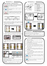
Refrigerant Connections – Thermodynamic Panel
The thermodynamic unit holds a pre-load of
R134a fluid.
WARNING
The refrigerant connections should be thermally
insulated in order to avoid burns and to ensure
the maximum performance of the equipment.
WARNING
The refrigerant connections should be dealt with
by a qualified technician holder of a professional
skills certificate for the purpose.
PIPE DIAMETER
VAPOUR
(suction)
LIQUID
(to the panel)
mm
inch
mm
inch
9,52
3/8’’
6,35
1/4’’
Diâmetro do
Tubo
(polegadas)
Binário
Aplicado
(Nm)
Chave nº
1/4”
14 a 16
19
3/8”
33 a 42
21
All connections should be insulated!
Refrigerant Connections - SolarBox
e
4
)
e
3
)
e
2
)
e
1
)
WARNING
INSTALLATION
(cont.)
INSTALLATION
(cont.)
Some of the steps involved here are exactly the same as the procedures
followed to connect the panel.
Cut the tube at the desired point with the end facing down. Clean any
frayed edges.
Flange the tube not forgetting to place the nut on the side of the tube
Tighten the nut a few turns with your hand and then use an appropriate
spanner to fully tighten the same as described above.
Once the connections have been concluded the user needs to check
there are no leaks. To this end, a load of nitrogen at a pressure of 10 bar
should be injected via the pressure tap (3-way valve).
Cover all the connections in soap foam to check the pressure on the
gauges is constant.
NITROGEN LOAD
VACUUM
a)
Always use connections, vacuum pump and gauges duly
adpated for R134a fluid.
b)
Only use a vacuum pump to remove the air and moisture
existing in the tube.
c)
Never use the system coolant to bleed the connection tubes.
d)
Keep the stop valves completely closed.
e)
Connect the hose from the vacuum pump to the 3-way valve.
f)
Create a vacuum with the pump connected to the pressure
tap to the 3-way valve (for 30 minutes) until a value of -1bar
has been attained.
g)
Once the vacuum process has been concluded (30 minutes),
turn off the pump and the gauge should always display the
same value.
h)
Turn off the gauge taps.
i)
After this vacuum process has been concluded, the two
valves should be opened to enable the coolant to circulate
throughout the system.
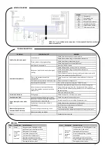
Legend:
1
3-way valve
2
Pressure tap
3
Valve sleeve
4
Valve needle
5
Hexagonal spanner
6
2-way valve
7
Conical nut
8
Liquid line (1/2”)
9
Gas line (1/2”)
a)
Prepare the copper tube, removing the protective caps from the ends.
b)
Place the end of the tube face-down, cut the tube at the desired
distance and clean any frayed edges.
c)
Remove the nuts from the connections and place them on the side of
the tube.
d )
Flange the tube with an appropriate tool, forming a cone, ensuring
there are no frayed edges or imperfections and the lengths of the
walls are the same.
e ) T ighten the nut a few turns with your hand, and then execute the
final tightening by twisting in accordance with the values illustrated in
the table
After creating the vacuum, do not remove the hoses
until the system has been fully pressurised by the
coolant.
The use of a thread sealant is recommended for all
existing thread connections.


