Eneo Almira R-01 Скачать руководство пользователя страница 11

7) 

Turn on the power supply to the recorder, 
and check the LED display. The Power LED 
should light up immediately. 

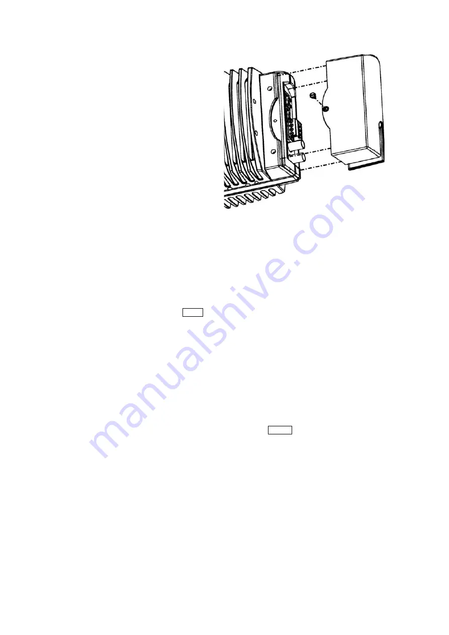
Fig. 2.4) Fitting the connector cover

8) 

After an interval of approximately one 
minute, when the recorder has successfully 
started up and completed its self-test, the 
second LED (marked with a heart symbol) 
will begin to flash. This shows that the 
recorder is working properly. If this LED d
not light up, or remains permanently on or 
off, there is a problem with the recorder. 

oes 

9) 

Once the Power LED is lit, and the 
‘heartbeat’ LED is pulsing, fit the connector 
cover using the two screws supplied (see 
Fig. 

2.4)

).  Installation is complete. 


2.5 D

ISCONNECTING THE RECORDER


You 

must

 shut down the recorder if you need to disconnect it or move it to a new location. Doing this 

will ensure that the drive is not damaged during the move, and no data is lost. Take care not to shut 
down the recorder by accident – nothing will be recorded while the disk is shut down. 

To 

shut down

 the recorder: 

1) 

Enter the menu system using the 

MENU

 key. 

2) 

In the main menu, use 

ST

 to go to 

Recorder 

and then press 

X

 to go to the next screen. 

3) 

In the 

Recorder

 menu, use 

ST

 to go to 

Advanced 

and then press 

X

 to go to the next screen.


4) 

In the 

Recorder Advanced

 menu, use 

ST

 to go to 

Disk Operations 

and then press 

X

 to go 

to the next screen.


5) 

Use 

ST

 to go to 

Shut Down Recorder 

and then press 

X

 to go to the next screen. 

6) 

A message appears saying 

Recording will be disabled until the recorder is 

reset. Are you sure?


7) 

The default response is 

No

: use 

T

 to choose 

Yes

, then press 

ENTER

 to confirm. The message 

Recorder disabled

 appears on screen, followed by 

Recorder Disconnected

. At the top 

right you will then see the message 

Shutting off the recorder

 followed by 

You can now 

turn off your recorder

.  At this point you can now remove power from the recorder and 

disconnect it from the camera. 

2.6 C

ONFIGURING THE RECORDER


To configure the recorder for continuous, event, or scheduled recording please refer to the camera 
manual (section 

6.2

). 

2.7 V

ERSIONS


To check version numbers for the recorder, please refer to the camera manual (section 

6.4

). 

Recorder Installation Manual v3.14 

Page 11

Содержание Almira R-01

Страница 1: ...1 Installation and Operating Instructions Digital Video Recorder Almira R 01...

Страница 2: ...yright holder details of whom can be obtained from Videor Technical This document is subject to change without written prior notice Whilst Videor Technical makes every effort to ensure the accuracy an...

Страница 3: ...of Conformity in accordance with the following EU standards has been made and is kept on file at the address shown on the last page The manufacturer declares that the product supplied with this docum...

Страница 4: ...Use this product only for the purpose for which it was designed as described in this manual and in the Eneo Almira user manual ENVIRONMENTAL CONDITIONS Storage 10 to 60 C 14 to 140 F The recorder sho...

Страница 5: ...1 REQUIREMENTS 7 2 2 BEFORE INSTALLING THE RECORDER 7 2 3 RECORDER INSTALLATION CHECKLIST 8 2 4 INSTALLING THE RECORDER 9 2 4 1 Wiring and installing the recorder 9 2 5 DISCONNECTING THE RECORDER 11...

Страница 6: ...IONS USED IN THIS MANUAL WARNING statements identify potential hazards and problems that can occur if the equipment is handled improperly WARNING Improper use of this equipment can cause severe bodily...

Страница 7: ...es as an NTP time server WARNING Do not replace the interconnection cable or use any other cable in its place doing so could damage the recorder and or the camera and will invalidate the warranty Powe...

Страница 8: ...ews for support bracket 3 M5 shakeproof washers 1 Plastic connector cover 2 M3 x 6mm 0 24 Pan Head Pozidriv screws for the connector cover 1 3m 9ft 10 interconnection cable 2 Ferrites 1 Installation m...

Страница 9: ...CORDER WARNING You must complete steps 1 to 5 of this installation before supplying power to the unit The recorder requires a 24V AC or DC power supply this is not the same as the camera which require...

Страница 10: ...e to do so will invalidate the warranty Fig 2 3 Connection panel 4 Connect the recorder to the camera using the cable supplied Be sure to connect the cable to the port marked Hi res video see Fig 2 3...

Страница 11: ...ecorder 1 Enter the menu system using the MENU key 2 In the main menu use ST to go to Recorder and then press X to go to the next screen 3 In the Recorder menu use ST to go to Advanced and then press...

Страница 12: ...t Locking Yes protect user definable sections and or events from erasure Motion Detection Tracking Yes accessed via camera Scene Analysis Yes as demo left luggage object removal and scene change Passw...

Страница 13: ...n 30W RS485 Pelco D auto sensing via camera Alarm Inputs 4 N O or N C via camera Alarm Output 1 N O or N C via camera Software Upgrade Upgrade enabled via LAN 10 100BaseT Time Date Generator Yes inclu...

Страница 14: ...20mm 4 75 78mm 3 07 78mm 3 07 40mm 1 575 105mm 4 13 118mm 4 65 40mm 1 575 Diameter 5 8mm 0 23 3 x tapped M5 thread 4 x tapped M5 thread 4 x tapped M5 thread Safety lanyard locating hole 4 x tapped M5...

Страница 15: ...istribution through specialised trade channels only VIDEOR TECHNICAL E Hartig GmbH Carl Zeiss Stra e 8 63322 R dermark Germany Tel 49 0 60 74 888 0 Fax 49 0 60 74 888 100 www videortechnical com Techn...

Отзывы: