background image

Mounting

Micropilot M FMR244 with FOUNDATION Fieldbus

14

Hauser

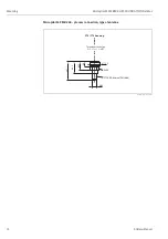
Measurement in a plastic tank

If the outer wall of the tank is made of a non-conductive material (e.g. GRP), microwaves can also 
be reflected off interfering installations outside the signal beam (e.g. metallic pipes (1), ladders (2), 
grates (3), …). Therefore, there should be no such interfering installations in the signal beam.

L00-FMR2xxxx-17-00-00-xx-013

Please contact Hauser for further information.

VH

00

VH

00

End

ress

+Ha

user

Endre

ss+Ha

user

- +

V

H

HAUSER

MICROPILO

T II

IP 65

Order Code:

Ser.-No.:

Messbereich

Measuring ra

nge

U 16...36 V D

C

4...20 mA

max. 20 m

Made in Ger

m

an

y             Maulb

urg

Made in Ger

m

an

y             Maulb

urg

T >70°C :

A

t >85°C

VH

00

VH

00

End

ress

+Ha

user

Endre

ss+Haus

er

- +

V

H

HAUSER

MICROPILO

T II

IP 65

Order Code:

Ser.-No.:

Messbereich

Measuring ra

nge

U 16...36 V D

C

4...20 mA

max. 20 m

Made in Ger

m

an

y             Maulb

u

rg

Made in Ger

m

an

y             Maulb

urg

T >70°C :

A

t >85°C

VH

00

VH

00

End

ress

+Ha

user

Haus

er

- +

V

H

HAUSER

MICROPILO

T II

IP 65

Order Code:

Ser.-No.:

Messbereich

Measuring ra

nge

U 16...36 V D

C

4...20 mA

max. 20 m

Made in Ger

m

an

y             Maulb

u

rg

Made in Ger

m

an

y             Maulb

u

rg

T >70°C :

A

t >85°C

1

2

3

Содержание Micropilot M FMR230

Страница 1: ...BA250F 00 en 05 06 Nr 52012494 Valid as of software version V 01 04 00 amplifier V 1 0 communication Operating Instructions Micropilot M FMR244 Level Radar 9 ...

Страница 2: ...M Brief operating instructions dome ceiling horizontal cyl bypass unknown DC 1 9 DC 1 9 4 DC 4 10 DC 10 standard calm surface add agitator input E see sketch input F see sketch only for bypass stilling well ok too small too big unknown manual displayed see sketch D and L are confirm or specify range suggestion 000 measured value Group selection 00 basic setup 01 safety settings 0C system parameter...

Страница 3: ...on 25 4 5 Post connection check 25 5 Operation 26 5 1 Quick operation guide 26 5 2 Display and operating elements 28 5 3 Local operation 31 5 4 Display and acknowledging error messages 34 5 5 FOUNDATION Fieldbus communication 35 6 Commissioning 52 6 1 Function check 52 6 2 Switching on the measuring device 52 6 3 Basic Setup 53 6 4 Basic Setup with the VU 331 55 6 5 Basic Setup with the ToF Tool 6...

Страница 4: ... instructions in this manual personnel must be authorised and suitably qualified The manual must have been read and understood and the instructions followed Modifications and repairs to the device are permissible only when they are expressly approved in the manual 1 3 Operational safety 1 3 1 Hazardous areas Measuring systems for use in hazardous environments are accompanied by separate Ex documen...

Страница 5: ...cate explosion hazardous areas Devices located in and wiring entering areas with the designation explosion hazardous areas must conform with the stated type of protection Safe area non explosion hazardous area Symbol used in drawings to indicate if necessary non explosion hazardous areas Devices located in safe areas still require a certificate if their outputs run into explosion hazardous areas E...

Страница 6: ...tion XA electrostatic charging 7 ATEX II 1 2 G EEx ia IIC T6 WHG XA IECEx Zone 0 1 Note safety instruction XA electrostatic charging 5 ATEX II 1 2 G EEx d ia IIC T6 XA IECEx Zone 0 1 Note safety instruction XA electrostatic charging G ATEX II 3 G EEx nA II T6 H ATEX II 1 2G EEx ia IIC T6 ATEX 3D XA Note safety instruction XA electrostatic charging S FM IS Cl I Div 1 Gr A D T FM XP Cl I Div 1 Group...

Страница 7: ...isplay on site D PROFIBUS PA w o display via communication L PROFIBUS PA Prepared for FHX40 remote display Accessory E FOUNDATION Fieldbus 4 line display VU331 envelope curve display on site F FOUNDATION Fieldbus w o display via communication M FOUNDATION Fieldbus Prepared for FHX40 remote display Accessory Y Special version 60 Housing A F12 Alu coated IP65 NEMA4X C T12 Alu coated IP65 NEMA4X sepa...

Страница 8: ...on of Instrument Functions you can be found on the enclosed CD ROM 2 3 Certificates and approvals CE mark declaration of conformity The device is designed to meet state of the art safety requirements has been tested and left the factory in a condition in which it is safe to operate The device complies with the applicable standards and regulations as listed in the EC declaration of conformity and t...

Страница 9: ...tion in tank free space Mark on process connector facing the nearest tank wall Installation in stilling well Mark on process connector pointed towards the slots or vent holes The housing can be turned 350 in order to simplify access to the display and the terminal compartment Allen key 4 mm 0 1 max torque 0 5 Nm G 1 or 1 NPT G 1 or 1 NPT mark at threaded boss mark at threaded boss AF 60 max torque...

Страница 10: ...e scope of supply matches your order 3 2 2 Transport Caution Follow the safety instructions and transport conditions for instruments of more than 18 kg Do not lift the measuring instrument by its housing in order to transport it 3 2 3 Storage Pack the measuring instrument so that is protected against impacts for storage and transport The original packing material provides the optimum protection fo...

Страница 11: ...s Hauser 11 3 3 Installation conditions 3 3 1 Dimensions Housing dimensions L00 F12xxxx 06 00 00 en 001 L00 T12xxxx 06 00 00 en 001 ENDRESS HAUSER 65 78 max 110 85 150 Ø 129 Aluminium F12 housing ENDRESS HAUSER 78 85 65 162 max 100 94 Ø 129 Aluminium T12 housing ...

Страница 12: ...th FOUNDATION Fieldbus 12 Endress Hauser Micropilot M FMR 244 process connection type of antenna L00 FMR244xx 06 00 00 en 005 147 Ø 39 Ø 71 5 84 5 62 5 39 PVDF Threaded connection G 1 or 1 NPT PTFE FDA listed TFM 1600 F12 T12 housing ...

Страница 13: ...y installations 1 like limit switches temperature sensors etc inside the signal beam refer to beam angle see Beam angle on Page 15 Symmetrical installations 2 i e vacuum rings heating coils baffles etc can also interfere with the measurement Optimization options Antenna size the bigger the antenna the smaller the beam angle the less interference echoes Mapping the measurement can be optimized by m...

Страница 14: ... 00 Endress H auser Endress H auser V H ENDRESS HAU SER MICROPILOT II IP 65 Order Code Ser No Messbereich Measuring range U 16 36 V DC 4 20 mA max 20 m Made in Germany Maulburg Made in Germany Maulburg T 70 C A t 85 C VH 00 VH 00 Endress H auser Endress H auser V H ENDRESS HAU SER MICROPILOT II IP 65 Order Code Ser No Messbereich Measuring range U 16 36 V DC 4 20 mA max 20 m Made in Germany Maulbu...

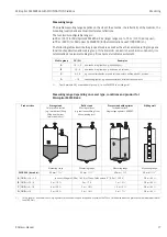
Страница 15: ...dB width Microwaves are also emitted outside the signal beam and can be reflected off interfering installations Beam diameter W as function of antenna type beam angle α and measuring distance D Antenna size horn diameter FMR 244 40 mm 1 L00 FMR2xxxx 14 00 06 de 027 Beam angle α 23 Measuring distance D Beam diameter W 40 mm 1 3 m 10 ft 1 22 m 4 07 ft 6 m 20 ft 2 44 m 8 14 ft 9 m 30 ft 3 66 m 12 21 ...

Страница 16: ...be chosen any closer than A see Fig to the tip of the antenna For FMR244 245 the end of measuring range should not be chosen closer than A see Fig to the tip of the antenna especially if there is development of condensate The smallest possible measuring range B depends on the antenna version see Fig The tank diameter should be greater than D see Fig the tank height at least H see Fig Note In case ...

Страница 17: ...nia NH3 as a medium of group A i e use FMR230 in a stilling well B 1 9 4 non conducting liquids e g benzene oil toluene C 4 10 e g concentrated acids organic solvents esters aniline alcohol acetone D 10 conducting liquids e g aqueous solutions dilute acids and alkalis Product class Storage tank Calm product surface e g intermittent filling filling from bottom immersion tubes Buffer tank Moving sur...

Страница 18: ...g in a tank please observe engineering hints on Page 13 and the following points Marker is aligned towards tank wall Install the device using the threaded boss AF 60 only Observe the max torque of 20 Nm After mounting the housing can be turned 350 in order to simplify access to the display and the terminal compartment For optimum measurement the horn antenna should extend below the nozzle Nozzle h...

Страница 19: ...tenna diameter Weld seam as smooth as possible and on the same axis as the slots Slots offset 180 not 90 Slot width respectively diameter of holes max 1 10 of pipe diameter de burred Length and number do not have any influence on the measurement At any transition i e when using a ball valve or mending pipe segments no gap may be created exceeding 1 mm The stilling well must be smooth on the inside...

Страница 20: ... FMR244xx 17 00 00 en 005 100 0 Micropilot M FMR 244 threaded connection G 1 or 1 NPT marker inside of holes deburred 1 10 Ø pipe stilling well with slots full bore ball valve 1 10 Ø pipe gap 1 mm 0 04 150 500 mm 6 20 Diameter of o of ball valve must always be equivalent to pipe diameter Avoid edges and constrictions pening ...

Страница 21: ...check After the measuring instrument has been installed perform the following checks Is the measuring instrument damaged visual check Does the measuring instrument correspond to the measuring point specifications such as process temperature pressure ambient temperature measuring range etc Is the flange marking correctly aligned Page 9 Have the flange screws been tightened up with the respective ti...

Страница 22: ...e connection between the antenna and the housing earth potential When you use the measuring system in hazardous areas make sure you comply with national standards and the specifications in the safety instructions XA s Make sure you use the specific cable gland On devices supplied with a certificate the explosion protection is designed as follows Housing F12 EEx ia Power supply must be intrinsicall...

Страница 23: ...e specific cable gland Connect up the Micropilot M as follows Before unscrew housing cover 2 at seperate connection room turn off the power supply Insert cable 3 through gland 5 Use screened twisted wire pair Only ground screening of the line 5 on sensor side Make connection see pin assignment Tighten cable gland 4 Screw on housing cover 2 Switch on power supply Before connection please note the f...

Страница 24: ... 70 C A MICROPILOT M ENDRESS HAUSER PTB 00 ATEX II 1 2 G EEx ia IIC T6 IP65 Foundation Fieldbus x x x x x x x x x x x x x x x x 1 3 4 11 8 7 Before connection please note the following Connect potential matching line to transmitter earth terminal before connecting up the device Tighten the locking screw It forms the connection between the antenna and the housing earth potential Foundation Fieldbus...

Страница 25: ... be ensured If potential equalisation is present between the individual grounding points ground the screening at each cable end or connect it to the device housing as short as possible If there are large differences in potential between grounding points the grounding should run via a capacitor that is suitable for high frequency use e g ceramic 10 nF 250 V Caution Applications which are subject to...

Страница 26: ...selected e g tank shape 002 with or b confirms selection appears in front of the selected parameter c confirms the edited value system quits Edit mode d interrupts selection system quits Edit mode a Press or to edit the first character of the e g empty calibr 005 b positions the cursor at the next character a until you have completed your input c if a symbol appears at the cursor press to accept t...

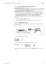
Страница 27: ...ns of the basic setup 00 function group include e g tank shape 002 medium property 003 process cond 004 empty calibr 005 etc If for example the application of the instrument is to be changed carry out the following procedure 1 Select the basic setup 00 function group 2 Select the tank shape 002 function where the existing tank shape is selected 5 1 2 Identifying the functions For simple orientatio...

Страница 28: ... means of a 500 mm cable Note To access the display the cover of the electronic compartment may be removed even in hazardous area IS and XP ENDRESS HAUSER E END RES S HA USE R MICR OPIL OT II END RES S HA USE R MICR OPIL OT II IP 65 IP 65 Order Code Ser No Order Code Ser No Messbe reich Measur ing range Messbe reich Measur ing range U 16 36 V DC 4 20 mA U 16 36 V DC 4 20 mA max 20 m max 20 m Made ...

Страница 29: ... 00 2 305m 0 00 ENDRESS HAUSER E Headline Position indicator Main value Unit Symbol Selection list Function groups Functions Help text Envelope curve Bargraph Sybmol Meaning ALARM_SYMBOL This alarm symbol appears when the instrument is in an alarm state If the symbol flashes this indicates a warning LOCK_SYMBOL This lock symbol appears when the instrument is locked i e if no input is possible COM_...

Страница 30: ...numeric value within a function Sor W Navigate downwards in the selection list Edit numeric value within a function X or Z Navigate to the left within a function group F Navigate to the right within a function group confirmation Oand F or Sand F Contrast settings of the LCD O and S and F Hardware lock unlock After a hardware lock an operation of the instrument via display or communication is not p...

Страница 31: ...on group The lock is shown on the display by the symbol and can be released again either via the display or by communication Hardware lock The instrument is locked by pressing the O and S and F keys at the same time The lock is shown on the display by the symbol and can only be unlocked again via the display by pressing the O and S and F keys at the same time again It is not possible to unlock the...

Страница 32: ...ock After pressing the O and S and F keys at the same time the user is asked to enter the unlock parameter 2457 for Foundation Fieldbus devices Caution Changing certain parameters such as all sensor characteristics for example influences numerous functions of the entire measuring system particularly measuring accuracy There is no need to change these parameters under normal circumstances and conse...

Страница 33: ...specific tank map is not deleted A linearisation is switched to linear although the table values are retained The table can be reactivated in the linearisation 04 function group List of functions that are affected by a reset The tank map can also be reset in the mapping 055 function of the extended calibr 05 function group This reset is recommended whenever an instrument with an unknown history is...

Страница 34: ...measuring error message is displayed Indicated by a flashing symbol For a description of the codes see Page 77 E Alarm Warning Configurable e g loss of echo level within the safety distance Indicated by a constant flashing symbol For a description of the codes see Page 77 5 4 1 Error messages Error messages appear as four lines of plain text on the display In addition a unique error code is also o...

Страница 35: ...m can be connected in the following ways A linking device makes the connection to higher order fieldbus levels e g High Speed Ethernet HSE possible An FOUNDATION Fieldbus H1 connecting card is needed for direct connection to a process control system Note Further information on FOUNDATION Fieldbus can be found in Operating Instructions BA013S FOUNDATION Fieldbus Overview Installation and Commission...

Страница 36: ...ctory foreseen for it Start the interface configuration tool Configure the interface Call the DD download routine Download the device descriptions ffo and sym files to the directory offered When the configuration is complete close the tool and the FOUNDATION Fieldbus stack if open The Micropilot M device descriptions can be ordered direct from Endress Hauser or downloaded from our website www endr...

Страница 37: ...E_ADDRESS can be changed A click on the name expands the device tree to show the function blocks available for it E H_MICROPILOT_M_XXXXXXXX PD_TAG the physical name of the device DEVICE_ID the unique device identifier NODE_ADDRESS the fieldbus node to which the device is connected is automatically allocated by the Configu rator Device_ID 452B48100F XXXXXXXX 452B48 ID code for Endress Hauser 100F I...

Страница 38: ...Operating Instructions BA013S FOUNDATION Fieldbus Overview Signal Characterizer Block SC s Operating Instructions BA013S FOUNDATION Fieldbus Overview Integrator Block IT s Operating Instructions BA013S FOUNDATION Fieldbus Overview Default Block configuration The input and output variables of the blocks can be interconnected by a network configuration tool e g NI Fieldbus configurator The figure be...

Страница 39: ...g mode of the block Actual indicates the current operating mode of the block Permitted states which operating modes are allowed Normal indicates the normal operating mode of the block The possible operating modes of the resources block are AUTO the block is operating as normal OOS the block is out of service If the resource block is out of service then all blocks within the device resource are for...

Страница 40: ...configuration parameters which are used to commission and calibrate the instrument They are identical to the functions of the operating menu except for the service parameters which are not accessible on the bus Thus the calibration procedure via the display module Chapter 6 4 is equally valid for a calibration via a network configuration tool A complete list of the configuration parameters can be ...

Страница 41: ...pipe diameter 007 24 PARTUBEDIAMETER 4 FloatingPoint RW static OOS echo quality 056 25 PARECHOQUALITY 1 Unsigned8 RO dynamic Auto OOS check distance 051 26 PARCHECKDISTANCE 1 Unsigned8 RW dynamic OOS range of mapping 052 27 PARSUPPRESSIONDISTANCE 4 FloatingPoint RW dynamic OOS start mapping 053 28 PARSTARTMAPPINGRECORD 1 Unsigned8 RW dynamic OOS pres map dist 054 29 PARPRESMAPRANGE 4 FloatingPoint...

Страница 42: ...ME 4 FloatingPoint RW dynamic Auto OOS unlock parameter 0A4 54 PAROPERATIONCODE 2 Unsigned16 RW non vol OOS measured dist 0A5 55 PARMEASUREDDISTANCE 4 FloatingPoint RO dynamic Auto OOS measured level 0A6 56 PARMEASUREDLEVEL 4 FloatingPoint RO dynamic Auto OOS detection window 0A7 57 PARDETECTIONWINDOW 1 Unsigned8 RW dynamic OOS application par 0A8 58 PARAPPLICATIONPARAMETER 1 Unsigned8 RO dynamic ...

Страница 43: ...espective function group in the operating menu A detailed description of them can be found in the Description of Instrument functions BA221F 00 en Instrument specific parameters 1 If MODE_BLK refuses to be changed to AUTO an error is present Control all parameters perform the required changes and try again to change MODE_BLK to AUTO Parameter Description MODE_BLK See description in Resource block ...

Страница 44: ...ds are identical to the respective function group in the operating menu A detailed description of them can be found in the Description of Instrument functions BA221F 00 en Instrument specific parameters 2 If MODE_BLK refuses to be changed to AUTO an error is present Control all parameters perform the required changes and try again to change MODE_BLK to AUTO Parameter Description MODE_BLK See descr...

Страница 45: ...red in the device Normally operation is resumed as soon as MODE BLK is set to AUTO Block administration parameters E H_MICROPILOT_M_XXXXXXXX RESOURCE_XXXXXX RB2 Sensor_XXXXXX TBRL ANALOG_INPUT_1_XXXXXX AI Parameter Description MODE_BLK See description in Resource block The possible operating modes of the Sensor block are AUTO the block is operating as normal MAN the block is operated with a manual...

Страница 46: ...Type or filtering V_TIME Comprises value and status Parameter Description CHANNEL Selects the measured value to be input to the analogue input block 0 no channel defined 1 primary value measured level volume 2 secondary value measured distance XD_SCALE Scales the Sensor block value in the required engineering units EU OUT_SCALE Scales the output value in the required engineering units EU L_TYPE Se...

Страница 47: ...would cause the alarm to activate when the level drops below 5 and to deactivate when the level rises to 7 HI_HI_PRI The priority 1 15 of the HI_HI alarm HI_HI_LIM Sets the HI_HI alarm limit in output engineering units HI_PRI The priority 1 15 of the HI alarm HI_LIM Sets the HI warning limit in output engineering units LO_PRI The priority 1 15 of the LO alarm LO_LIM Sets the LO warning limit in ou...

Страница 48: ...o Out of Service Reset the device to factory values by using the function RESTART Defaults this function may also be available with a right hand click on the device name If appropriate assign a tag description TAG_DESC Set MODE_BLK_TARGET to Auto 3 Configure the Sensor block If appropriate change the block tag right hand click on tree Set MODE_BLK_TARGET to Out of Service If appropriate assign a t...

Страница 49: ... 900 Signal Characterizer Function Block 1000 Integrator Function Block 1100 Sensor Block 2000 Diagnostic Block 2200 Display Block 2400 Object Start Index View Objects Resource Block 3000 View Objects Analog Input 1 Function Block 3010 View Objects Analog Input 2 Function Block 3020 View Objects PID Function Block 3030 View Objects Arithmetic Function Block 3040 View Objects Input Selector Functio...

Страница 50: ...ollowing functions Online configuration of transmitters Signal analysis via envelope curve Tank linearisation Loading and saving of instrument data Upload Download Documentation of measuring point Note The parameters of the Analog Input block are presently not accessible via ToF Tool Note ToF Tool operation of the Micropilot M is not possible via FOUNDATION Fieldbus Instead the PC or Laptop must b...

Страница 51: ...lope curve L00 FMR2xxxx 20 00 00 en 008 Connection options Service interface with adapter FXA193 RS232C FXA291 USB Hinweis The Micropilot M can also be operated locally using the keys If operation is prevented by the keys being locked locally parameter entry via communication is not possible either ...

Страница 52: ...n the instrument is switched on for the first time the following messages appear on the display After 5 s the following message appears After 5 s or after you have pressed F the following message appears Select the language this message appears the first time the instrument is switched on Select the basic unit this message appears the first time the instrument is switched on The current measured v...

Страница 53: ...eiling measuring cond Unknown measuring cond Standard pipe diameter mapping safety settings linearisation extended calibr empty calibr full calibr for bypass stilling well description see BA 221F E empty calibr zero setting in 005 F full calibr span setting in 006 D distance distance flange product display in 0A5 L level display in 0A6 SD safety distance setting in 015 basic setup standard option ...

Страница 54: ...mapping 053 prompt you to confirm your data entries Press O or S to select YES and press F to confirm The function is now started If you do not press a key during a configurable time period function group display 09 an automatic return is made to the home position measured value display Note The instrument continues to measure while data entry is in progress i e the current measured values are out...

Страница 55: ...ustomer unit 042 function The number of digits after decimal point can be selected in the no of decimals 095 function 6 4 1 Function group basic setup 00 Function tank shape 002 This function is used to select the tank shape Selection dome ceiling horizontal cyl bypass stilling well also for Wave Guide antenna use flat ceiling sphere L00 FMR2xxxx 14 00 06 en 007 ENDRESS HAUSER E ENDRESS HAUSER E E...

Страница 56: ...4 DC 4 10 DC 10 ENDRESS HAUSER E Product class DC εr Examples A 1 4 1 9 non conducting liquids e g liquefied gas 1 1 Treat Ammonia NH3 as a medium of group A i e use FMR 230 in a stilling well B 1 9 4 non conducting liquids e g benzene oil toluene C 4 10 e g concentrated acids organic solvents esters aniline alcohol acetone D 10 conducting liquids e g aqueous solutions dilute acids and alkalis ...

Страница 57: ...e values The averaging filters and output damping are set to high values steady meas value precise measurement slower reaction time Special filters to smooth the input signals are emphasised smoothed meas value medium fast reaction time agitator fast change test no filter Agitated surfaces with possible vortex due to agitators Rapid change of level particularly in small tanks All filters can be sw...

Страница 58: ...s function is used to enter the distance from the flange reference point of the measurement to the minimum level zero L00 FMR2xxxx 14 00 06 en 008 Caution For dish bottoms or conical outlets the zero point should be no lower than the point at which the radar beam hits the bottom of the tank ENDRESS HAUSER E ...

Страница 59: ...l to the maximum level span L00 FMR2xxxx 14 00 06 en 009 Note If bypass or stilling well was selected in the tank shape 002 function the pipe diameter is requested in the following step Note For FMR 244 the end of measuring range should not be chosen closer than 150 mm 6 inch to the tip of the antenna especially if there is development of condensate ENDRESS HAUSER E ...

Страница 60: ...e stilling well or bypass pipe L00 FMR2xxxx 14 00 00 en 011 Microwaves propagate more slowly in pipes than in free space This effect depends on the inside diameter of the pipe and is automatically taken into account by the Micropilot It is only necessary to enter the pipe diameter for applications in a bypass or stilling well ENDRESS HAUSER E 100 0 ø 100 0 ø ...

Страница 61: ... check distance 051 This function triggers the mapping of interference echoes To do so the measured distance must be compared with the actual distance to the product surface The following options are available for selection Selection distance ok dist too small dist too big dist unknown manual L00_FMR2xxxxx 14 00 06 en 010 distance ok mapping is carried out up to the currently measured echo The ran...

Страница 62: ...ng already exists it is overwriten up to the distance specified in range of mapping 052 Beyond this value the existing mapping remains unchanged Function range of mapping 052 This function displays the suggested range of mapping The reference point is always the reference point of the measurement see Page 53 ff This value can be edited by the operator For manual mapping the default value is 0 m Fu...

Страница 63: ... are displayed Check whether the values correspond to the actual level or the actual distance The following cases can occur Distance correct level correct continue with the next function check distance 051 Distance correct level incorrect Check empty calibr 005 Distance incorrect level incorrect continue with the next function check distance 051 ENDRESS HAUSER E After 3 s the following message app...

Страница 64: ... curve 0E2 This function defines whether the envelope curve is read as a single curve or cyclic Note If the cyclical envelope curve is active in the display the measured value is refreshed in a slower cycle time It is therefore recommended to exit the envelope curve display after optimising the measuring point Note An orientation of the Micropilot can help to optimise measurement in applications w...

Страница 65: ... 00 en 004 Horizontal Zoom mode Firstly go into the envelope curve display Then press O or S to switch to the envelope curve navigation You are then in Horizontal Zoom mode Either or is displayed O increases the horizontal scale S reduces the horizontal scale L00 FMxxxxxx 07 00 00 yy 007 minimum distance of the plot maximum distance of the plot distance of evaluated echo interference echo evaluate...

Страница 66: ... now have the following options O increases the vertical scale S reduces the vertical scale The display icon shows the current zoom factor to L00 FMxxxxxx 07 00 00 yy 009 Exiting the navigation Press F again to run through the different modes of the envelope curve navigation Press O and S to exit the navigation The set increases and shifts are retained Only when you reactivate the recording curve ...

Страница 67: ... the ToF Tool operating program and establish a connection Select the basic setup function group in the navigation bar The following display appears on the screen Basic Setup step 1 4 Status image Enter the measuring point description TAG number L00 FMR2xxxx 20 00 00 en 001 Note Each parameter that is changed must be confirmed with the RETURN key The Next button moves you to the next screen displa...

Страница 68: ...ee Page 55 medium property for a description see Page 56 process cond for a description see Page 57 L00 FMR2xxxx 20 00 00 en 002 Basic Setup step 3 4 If dome ceiling is selected in the tank shape function the following display appears on the screen empty calibr for a description see Page 58 full calibr for a description see Page 59 L00 FMR2xxxx 20 00 00 en 003 ...

Страница 69: ...Page 58 full calibr for a description see Page 59 L00 FMR2xxxx 20 00 00 en 004 If stilling well or bypass is selected in the tank shape function the following display appears on the screen empty calibr for a description see Page 58 full calibr for a description see Page 59 diameter of bypass stilling well for a description see Page 60 L00 FMR2xxxx 20 00 00 en 005 Note You can also specify the pipe...

Страница 70: ...isplay appears on the screen empty calibr for a description see Page 58 full calibr for a description see Page 59 L00 FMR2xxxx 20 00 00 en 006 Basic Setup step 4 4 This step starts the tank mapping The measured distance and the current measured value are always displayed in the header A description is given on Page 61 L00 FMR2xxxx 20 00 00 en 007 ...

Страница 71: ...a heavy interference echo an orientation of the Micropilot can help optimise the measurement increase of the useful echo reduction of the interference echo see Orientation of the Micropilot on Page 81 When using the Wave Guide antenna No orientation is required 6 5 2 User specific applications operation For details of setting the parameters of user specific applications see separate documentation ...

Страница 72: ...rrying out repairs to Ex approved devices please note the following Repairs to Ex approved devices may only be carried out by trained personnel or by Endress Hauser Service Comply with the prevailing standards national Ex area regulations safety instructions XA and certificates Only use original spare parts from Endress Hauser When ordering a spare part please note the device designation on the na...

Страница 73: ...commended for outdoor mounting order code 543199 0001 The shipment includes the protective cover and tension clamp L00 FMR2xxxx 00 00 06 en 001 ENDRESS HAUSER MICROPILOT II ENDRESS HAUSER MICROPILOT II IP 65 IP 65 Order Co de Se r No Order Co de Se r No Me ssbereich Me asuring range Me ssbereich Me asuring range U 16 3 6 V DC 4 20 mA U 16 3 6 V DC 4 20 mA ma x 20 m ma x 20 m Made in Germany Maulbu...

Страница 74: ...mapilot M FMG60 Levelflex M FMP4x Micropilot FMR130 FMR131 Micropilot M FMR2xx Micropilot S FMR53x FMR540 Prosonic FMU860 861 862 Prosonic M FMU4x Tank Side Monitor NRF590 with additional adapter cable ToF Adapter FXA291 The ToF Adapter FXA291 connects the Commubox FXA291 via the USB interface of a personal computer or a notebook to the following Endress Hauser instruments Cerabar S PMC71 PMP7x De...

Страница 75: ...min 30 96 88 160 8 5 118 180 Micropilot M Levelflex M Prosonic M Separate housing FHX 40 IP 65 Cable 122 150 80 Wall mounting without mounting bracket Pipe mounting mounting bracket and plate supplied optionally s product structure pipe Max cable length 20 m 65 ft Temperature range 30 C 70 C 22 F 158 F Degree of protection IP65 acc to EN 60529 NEMA 4 Materials Housing AlSi12 cable glands nickle pl...

Страница 76: ... Ready Yes No Possibly defective electronics Contact E H Service HART communication does not function Is the communication resistor installed according to the OM Install the resistor see the OM Communication ok Ready Ready ok Yes Yes No No Connect the Commubox see the OM Communication ok Ready Set the switch correctly Communication ok Ready Ready Contact E H Service Contact E H Service Contact E H...

Страница 77: ...d checksum of stored data not correct restart download of data A121 electronics defect no factory calibration existant EPROM defective contact service W153 initialising please wait initialisation of electronics wait some seconds if warning prevails power off device and power on again A155 electronics defect hardware problem reset if alarm prevails after reset exchange electronics A160 checksum err...

Страница 78: ...t up on antenna check installation optimize orientation of antenna clean antenna cf OM E651 level in safety distance risk of overspill level in safety distance alarm will disappear as soon as level leaves safety distance E671 linearisation ch1 not complete not usable linearisation table is in edit mode activate linearisation table Code Description Possible cause Remedy ...

Страница 79: ...ement in bypass or stilling well yes 1 Is bypass or stilling well selected in tank shape 002 2 Is the pipe diameter 007 cor rect no Is an offset 057 active yes 1 offset 057 correctly set no An interference echo may have been evalua ted yes 1 Carry out tank mapping basic setup No change off measured value on filling emptying L00 FMR2xxxx 19 00 00 en 014 Interference echo from installations nozzle o...

Страница 80: ...pe 002 e g dome ceiling or horizontal cyl 2 In the range of the blocking dist 059 there is no echo evaluation Adapt the value 3 If possible do not select central installation position see Page 13 4 Perhaps use a stilling well see Page 19 E 641 loss of echo L00 FMR2xxxx 19 00 00 en 018 Level echo is too weak Possible causes Rough surface due to filling emptying Agitator running Foam yes 1 Check app...

Страница 81: ...pping uses a somewhat lower level that causes an increase in the strength of the measuring signal Proceed as follows Warning Subsequent alignment can lead to personal injury Before you unscrew or loosen the process connection make sure that the vessel is not under pressure and does not contain any injurious substances 1 It is best to empty the container so that the bottom is just covered However a...

Страница 82: ...ss Hauser L00 FMRxxxxx 19 00 00 en 004 Fig 7 Vessel empty no interference echo L00 FMRxxxxx 19 00 00 en 005 Fig 8 Vessel empty interference echo obtained 7 Fix the flange or threaded boss in this position If necessary replace the seal 8 Carry out tank mapping see Page 61 ...

Страница 83: ...number also appears on each spare part Installation instructions are given on the instruction card that is also delivered Spare parts Micropilot M FMR 244 F12 housing with combined wiring and electronics compartment L00 FMR244xx 00 00 06 xx 001 ENDRESS HAUSER MICROPILOT II IP 65 Order Code Ser No Messbereich Measuring range U 16 36 V DC 4 20 mA max 20 m Made in Germany Maulburg Made in Germany Mau...

Страница 84: ...2 Aluminium window gasket 517391 0011 Cover F12 T12 Aluminium coated gasket 30 Electronics 71023757 Electronics FMR23x FMR24x Ex HART 4 0 71023758 Electronics FMR23x FMR24x Ex PA 4 0 71023759 Electronics FMR23x FMR24x Ex FF 4 0 31 HF module 52006025 HF module MICROPILOT M 26 GHz 35 Terminal module power supply board 52006197 Terminal module 4pole HART 2 wire with cable connection 52012156 Terminal...

Страница 85: ...N Fieldbus Trouble shooting Endress Hauser 85 65 Sealing kit 535720 9010 consists of 2 x gasket Pg13 5 FA 2 x O ring 17 0x2 0 EPDM 1 x O ring 49 21x3 53 EPDM 2 x O ring 17 12x2 62 FKM 1 x O ring 113 9x3 63 EPDM 1 x O ring 72 0x3 0 EPDM ...

Страница 86: ...th separate wiring and electronics compartment L00 FMR244xx 00 00 06 xx 002 ENDRESS HAUSER MICROPILOT FMR IP 65 Order Code Ser No Messbereich Measuring range U 16 36 V DC 4 20 mA max 20 m Made in Germany Maulburg Made in Germany Maulburg T 70 C A t 85 C ENDRESS HAUSER ENDRESS HAUSER 10 65 65 25 65 11 30 35 40 31 12 12 20 65 50 ...

Страница 87: ...ket 517391 0011 Cover F12 T12 Aluminium coated gasket 25 Cover for terminal compartment 518710 0020 Cover T3 T12 Aluminium coated gasket 30 Electronics 71023757 Elektronik FMR23x FMR24x Ex HART 4 0 71023758 Elektronik FMR23x FMR24x Ex PA 4 0 71023759 Elektronik FMR23x FMR24x Ex FF 4 0 31 HF module 52006025 HF module MICROPILOT M 26 GHz 35 Terminal module power supply board 52013302 Terminal module...

Страница 88: ...44 with FOUNDATION Fieldbus 88 Endress Hauser 65 Sealing kit 535720 9010 consists of 2 x gasket Pg13 5 FA 2 x O ring 17 0x2 0 EPDM 1 x O ring 49 21x3 53 EPDM 2 x O ring 17 12x2 62 FKM 1 x O ring 113 9x3 63 EPDM 1 x O ring 72 0x3 0 EPDM ...

Страница 89: ...code if possible Operating time of the device 9 7 Disposal In case of disposal please seperate the different components according to their material consistence 9 8 Software history 9 9 Contact addresses of Endress Hauser The addresses of Endress Hauser are given on the back cover of this operating manual If you have any questions please do not hesitate to contact your E H representative Software v...

Страница 90: ...s Local display Error symbol see Page 29 Plain text display Current output Digital interface Linearization The linearization function of the Micropilot M allows the conversion of the measured value into any unit of length or volume Linearization tables for calculating the volume in cylindrical tanks are pre programmed Other tables of up to 32 value pairs can be entered manually or semi automatical...

Страница 91: ...le illustrates this measured error for a few typical gases vapors with regard to the distance a positive value means that too large a distance is being measured Note When the pressure is known and constant this measured error can for example be compensated by means of linearization Gas phase Temperature Pressure C F 1 bar 14 5 psi 10 bar 145 psi 50 bar 725 psi 100 bar 1450 psi 160 bar 2320 psi Air...

Страница 92: ...pends on the medium and the reflectivity mainly determined by the dielectric constant εr If the medium tends to cause contamination and deposits cleaning on a regular basis is recommended Care has to be taken not to damage the antenna in the process of a mechanical or hose down cleaning eventually connection for cleaning liquid The material compatibility has to be considered if cleaning agents are...

Страница 93: ...ontrol in the chemical industry Ex approval XA 105F E Installation Micropilot M FMR 2xx T12 PTFE antenna non conductive EExd ia IIC T6 PTB 00 ATEX 2117 X Equipment marking II 1 2 G XA 106F E Installation Micropilot M FMR 2xx F12 PTFE antenna non conductive EEx ia IIC T6 PTB 00 ATEX 2117 X Equipment marking II 1 2 G XA 206F B Installation Micropilot M FMR 2xx F23 PTFE antenna non conductive EEx ia ...

Страница 94: ... Note This supplementary documentation can be found on our product pages on www endress com Supplementary Documentation Technical Information TI345F 00 en Operating Instructions Description of instrument functions BA221F 00 en Safety Manual Functional Safety Manual SD150F 00 en Certificate German WHG ZE244F 00 de ...

Страница 95: ...Micropilot M FMR244 with FOUNDATION Fieldbus Technical data Endress Hauser 95 ...

Страница 96: ...distance ok dist too small manual dist unknown dist too big back to home enter time default 100 s clear last error protocol sw no plot settings envelope curve env curve FAC env curve cust map ramp span min empty calibr enter value linearisation range of mapping pres Map dist input of mapping range is displayed format display decimal reset for reset code see manual recording curve single curve cycl...

Страница 97: ...l download mode diameter vessel in safety dist alarm self holding warning check distance distance ok dist too small manual dist unknown dist too big offset will be added to the measured level ackn alarm no yes range of mapping input of mapping range output damping Antenna extens enter value default 5 s length FAR10 for FMR230 only application par Return to Group Selection not modified modified sta...

Страница 98: ...us 98 Endress Hauser 11 2 Description of functions Note A detailed description of the function groups functions and parameters is given in the documentation BA 221F 00 en Description of the instrument functions of the Micropilot M on the enclosed CD ROM ...

Страница 99: ... unambiguous signal identification is accomplished by the PulseMaster software based on many years of experience with time of flight technology The mm accuracy of the Micropilot S could be achieved with the patented algorithms of the PhaseMaster software The distance D to the product surface is proportional to the time of flight t of the impulse D c t 2 with c being the speed of light Based on the...

Страница 100: ...tion Fieldbus The system integration via Foundation Fieldbus is described in Chapter 5 5 On site operation with display and operating module VU331 with a Personal Computer FXA193 RS232C or FXA291 and ToF Adapter FXA291 USB and the operating software ToF Tool FieldTool Package respectively FieldCare The ToF Tool is a graphical operating software for instruments from Endress Hauser that operate base...

Страница 101: ...n in stilling well 9 19 installation in tank 9 18 interference echo 81 interference echoes 61 K key assignment 30 L level 53 lock 31 32 M maintenance 72 mapping 61 62 70 71 maximum measured error 90 Measurement in a plastic tank 14 measuring conditions 16 measuring principle 99 medium property 56 68 mounting 9 N nameplate 6 notes on safety conventions and symbols 5 O operatin menu 96 operating men...

Страница 102: ...FOUNDATION Fieldbus Index 102 Endress Hauser ToF Tool 50 67 71 96 trouble shooting 76 trouble shooting instructions 76 turn housing 9 21 U unlock parameter 31 32 V VU 331 55 64 W warning 34 weather protection cover 73 wiring 22 ...

Страница 103: ...____________________________________________ ______________________________________________________________________________________________________________ We hereby certify that this declaration is filled out truthfully and completely to the best of our knowledge We further certify that the returned parts have been carefully cleaned To the best of our knowledge they are free of any residues in da...

Страница 104: ...www endress com worldwide BA250F 00 en 05 06 52012494 CCS FM SGML 6 0 ProMoDo 52012494 ...

Отзывы: