1616-964-12
Date: 7/27/2011
Rev. 2.1
The SOP dialer should be powered through either a bright/dim switch, or through a
rheostat. If not connecting the dialer to a dimmer buss, connect to 14/28 VDC
through a circuit breaker. The dialer is entirely passive and can be dimmed through
a range of 4-11VDC. If two or more dialers are to be installed, they may be wired in
parallel with the addition of isolation diodes on the dialer lines, A1, A2, and A4. See
wiring drawings for details.
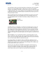
The 11 Position Dialer has the annunciators dimmed from a separate source as the
back lighting on the face plate. By default, they are wired separately, but can be
connected together either externally or internally by adding a shorting bar across
header J2.
The MMU S/N 001 to 100 lighting is controlled from the lighting buss, but the unit
does not draw current from the buss. The control is used to “follow” the dimmer
buss voltage and when this voltage gets within 20% of the low end of the scale, the
unit will illuminate to full brightness for day light use. This is designed for aircraft
that loose dimmer voltage when the dimmer is turned off. S/N 101 and later, due to
a change in the display, the only dimming allowed is through the face plate knob and
menu.
MMU and MMU II - P1 are wired identical with the exception listed above on the
dimmer. MMU II also dims through a menu using the knob. MMU II P2 is identical
to the connector on the PTA12-X00. Either a MMU or a PTA-12 can be removed and
the correct dash number MMU II be installed in its place.
See paragraph below, for installations that use a MMU and a GPS that does not
supply altitude data, the serializer may be input through the diagnostics port. This
should be done using the 9 pin connector as on the drawings, so the serializer may
be disconnected when time to connect a PC.
The best way to load a MSet into the MMU II is through the connector P/J19 as
shown in the installation drawings. This is a pigtail that is to be provided to the
customer so the MSet can be loaded without removing the MMU II from the
aircraft. Please make sure this connector is provided in all the installations.
J2 jumper
shown installed
4 - 6
Содержание Sky Connect Series
Страница 8: ...1616 964 12 Date 7 27 2011 Rev 2 1 Figure 1 Tracker Communication Concept Drawing 1 2 ...
Страница 20: ...1616 964 12 Date 7 27 2011 Rev 2 1 This page intentionally left blank 2 6 ...
Страница 36: ...1616 964 12 Date 7 27 2011 Rev 2 1 Figure 10 MMU II Figure 11 MMU 4 4 ...
Страница 68: ......
Страница 69: ......

