

63 mm
THIS WAY
UP WHEN
WALL
MOUNTING
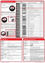
TONE
TONE TYPE
TONE DESCRIPTION / APPLICATION
1.
970Hz
O-O-O-O-O
18
2.
800Hz/970Hz
@
2Hz
O-O-O-O-|
1
3.
800Hz - 970Hz @ 1Hz
O-O-O-|-O
1
4.
970Hz 1s OFF / 1s ON
O-O-O-|-|
1
5. 970Hz, 0.5s / 630Hz, 0.5s
O-O-|-O-O
4
6.
554Hz, 0.1s / 440Hz, 0.4s (AFNOR NF S 32 001)
O-O-O-|-|
1
7.
500 - 1200Hz, 3.5s / 0.5s OFF (NEN 2575:2000)
O-O-|-O-|
1
8.
420Hz 0.625s ON / 0.625s OFF (Australia AS1670 Alert tone)
O-O-|-|-|
9
9.
500 - 1200Hz, 0.5s / 0.5s OFF x 3 / 1.5s OFF (AS1670 Evacuation)
O-|-O-O-O
1
10.
550Hz / 440Hz @ 0.5Hz
O-|-O-O-|
19
11.
970Hz, 0.5 ON / 0.5s OFF x 3 / 1.5s OFF (ISO 8201)
O-|-O-|-O
1
12.
2850Hz, 0.5s ON / 0.5s OFF x 3 / 1.5s OFF (ISO 8201)
O-|-O-|-|
1
13.
1200Hz - 500Hz @ 1Hz (DIN 33 404)
O-|-|-O-O
1
14.
400Hz
O-|-|-O-|
18
15.
550Hz, 0.7s / 1000Hz, 0.33s
O-|-|-|-O
1
16.
1500Hz - 2700Hz @ 3Hz
O-|-|-|-|
1
17.
750Hz
|-O-O-O-O
1
18.
2400Hz
|-O-O-O-|
1
19.
660Hz
|-O-O-|-O
18
20.
660Hz 1.8s ON / 1.8s OFF
|-O-O-|-|
19
21.
660Hz 0.15s ON / 0.15s OFF
|-O-|-O-O
19
22.
510Hz, 0.25s / 610Hz, 0.25s
|-O-|-O-|
1
23.
800 / 100Hz 0.5s each (1Hz)
|-O-|-|-O
1
24.
250Hz - 1200Hz @ 12Hz
|-O-|-|-|
1
25.
500Hz - 1200Hz @ 0.33Hz
|-|-O-O-O
1
26.
2400Hz - 2900Hz @ 9Hz
|-|-O-O-|
18
27.
2400Hz - 2900Hz @ 3Hz
|-|-O-|-O
18
28.
800Hz - 970Hz @100Hz
|-|-O-|-|
1
29.
800Hz - 970Hz @ 9Hz
|-|-|-O-O
1
30.
800Hz - 970Hz @ 3Hz
|-|-|-O-|
1
31.
800Hz, 0.25s ON / 1s OFF
|-|-|-|-O
1
32.
500Hz - 1200Hz, 3.75s / 0.25s OFF (AS2220)
|-|-|-|-|
8
SIZE C
SIZE C
SIZE C
SIZE AA
SIZE AA
SIZE AA
Wireless Sounder / Visual Indicator
Installation Guide
1 Pre installation
4 Power device
Cut out section
(shaded area)
To unlock the device,
insert a 1.5 mm allen key
to depress the locking clip
and turn anticlockwise to
release.
Unclip the battery retaining plate from the wireless module.
When fitting / replacing batteries; observe correct polarity,
using only specified batteries.
Connect the power jumper across the PIN header.
3 Fix mounting plate
2 Components
Part no Product description
device
unpowered
(pins unlinked)
device
powered
(both pins linked)
!
Installation must conform to applicable local installation
codes and should only be installed by a fully trained
competent person.
Ensure that the device is installed as per the site survey.
The use of a non-metallic spacer should be considered if
mounting the device on to a metal surface.
Do NOT Press the Log On button on a pre-programmed device,
as this will cause communication with the Control Panel to be
lost. Should this happen, delete the device from the system
and add it back on.
This device contains electronics that may be susceptible to
damage from Electrostatic Discharge (ESD). Take appropri-
ate precautions when handling electronic boards.
Sounder/visual indicator variant
Wireless module
Mounting plate
1
4
2
Remove the mounting plate by turning the device
ANTICLOCKWISE, to release it from the mounting plate.
3
5 Optional device locking
6 Configuration
To lock the sounder into
the wireless module,
remove the cut out section
as shown.
Use both mounting holes.
Use suitable fasteners and fixings.
Once powered, reassemble the device.
When wall mounting, ensure the mounting plate is fitted in the
orientation shown.
See the Specification section for compliance information.
CPR
FC-171-001
FC-171-002
FC-172-001
FC-172-002
FC-173-002
FC-173-003
FC-173-004
FC-178-002
FC-178-003
FC-178-004
White Wireless Sounder Base Only
[2]
Red Wireless Sounder Base Only
[2]
White Sounder Only
[1]
Red Sounder Only
[1]
Red Sounder Visual Indicator Only
[1]
Amber Sounder Visual Indicator Only
[1]
Clear Sounder Visual Indicator Only
[1]
Red Visual Indicator Only
Amber Visual Indicator Only
Clear Visual Indicator Only
1
4
2
Battery retaining plate
3
Example shown:
FC-172-001
FC-171-001
©2021 EMS Ltd. All rights reserved Page 1 of 2
TSD047-99 Iss 16 23/11/2021 AJM
The device’s loop address is configured within the user interface’s
menu structure.
Refer to the programming manual for full programming details.
Free to download from
www.emsgroup.co.uk
FireCell = MK98
Fusion = TSD062
WZM = TSD143