Safety
Information
Introduction
Product
information
System
design
Mechanical
installation
Electrical
installation
Getting
started
Optimisation
Parameters
Technical
data
Component
sizing
Diagnostics
44
Unidrive SP Regen Installation Guide
www.controltechniques.com Issue Number: 2
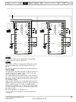
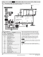
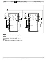
Figure 4-8 EMC filter
If the cable length exceeds the maximum cable length with additional
cooling, Control Techniques Technical Support must be consulted.
Whether or not an EMC filter is required is dependent upon the user
requirements and the AC supply network. For further details refer to
section 6.4
EMC (Electromagnetic compatibility)
4.6.4 Line to ground capacitors for multi-drive
systems
Selection of line to ground capacitors for regen systems with long
cables.
In order to select the appropriate capacitors, the rms value of the current
line to ground, the AC supply voltage and minimum capacitance values
are required.
A minimum capacitance value of 1
µ
F per phase should be used with the
final capacitance value being determined by the level of current line to
ground. In practice, to carry the required level of current the capacitor
will generally have a higher capacitive value. The current rating of the
capacitors should be at a high frequency such as 100kHz at the relevant
supply voltage. Polypropylene type capacitors (x type) are the most
suitable because of their low loss at high frequency.
The rms value of the current can be estimated from the following
formula:
Where:
k
is 1 for simple rectifier-input systems,
√
2 for regen systems
V
DC
is DC bus voltage
∑
lf
s
is the sum of the products of motor cable lengths and switching
frequencies of all drives in the system, including in the case of
regenerative systems the Regen drive with the total DC cable length
l
is total cable length in m
f
s
is switching frequency in kHz
If all drives operate at 3kHz, the expression can be simplified to:
I
RMS
=
4.85
x
10
-4
x K x V
DC
x
√
l
Example
A regen system operating with a supply of 400Vac giving a DC bus
voltage of 620V at 3kHz switching frequency and a cable length of 1km
( DC) has an
I
RMS
of:
I
RMS
=
4.85
x
10
-4
x K x V
DC
x
√
l
I
RMS
= 4.85
x
10
-4
x
√
2
x
620
x
√
1.000
I
RMS
=
13.4A
The
I
RMS
is the total current line to ground, therefore each capacitor will
have to carry 4.5A.
When using an EMC filter, a switching frequency filter must
also be used to protect the EMC filter from overload.
EMC
filter
Switching
frequency
filter inductor
Line to
ground
capacitance
Regen
inductor
E
Switching
frequency
filter capacitor
NOTE
CAUTION
I
RMS
2.8 10
4
–
K V
DC
×
×
Σ
lf
s
×
=
Ground leakage current
The value of capacitance required means that the ground
leakage current exceeds the usual safety limit of 3.5mA. The
user should be aware of the high leakage current. A
permanent fixed ground connection must be provided to the
system.
Discharge time
Resistors must be fitted in parallel with the capacitors to
ensure that they discharge when the supply is removed. The
resistor values should be chosen so that the discharge time
is no longer than for the drive itself. Typically values of about
5M
Ω
are suitable, and are high enough not to cause the
system to fail a simple insulation test.
WARNING
WARNING
Содержание SP1201
Страница 219: ......
Страница 220: ...0471 0029 02 ...

