Functional Description
RTM-ATCA-F140 Installation and Use (6806800M97A
)
56
4.8.10 FPGA Configuration
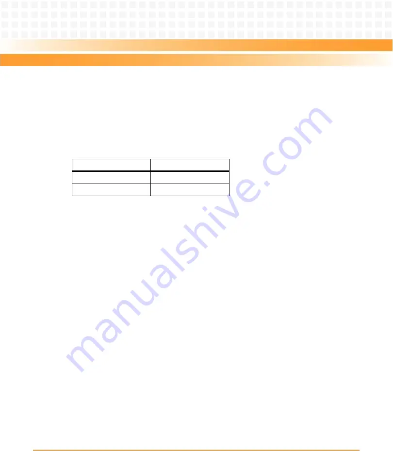
The RTM FPGA configuration is loaded at power-up from one of two SPI Flash devices. One
device is writable/upgradeable and the other is non-writable/golden for recovery purposes.
The selection is which device is used is controlled by switch S1 position 1, according to the
following table.
The configuration Flash devices can be field upgraded using a SPI-controlled Flash programmer
in the FPGA.
4.9
Reset Scheme
The front blade provides a single reset signal, RTM_RST#, over the zone 3 connectors. This
signal is asserted when a master reset of the front blade occurs.
RTM_RST# directly resets the RTM FPGA. The BCM8727, BCM84754, BCM84740, and QSFP+
slot are reset from a secondary reset generated by the RTM FPGA. This allows software control
of the PHY and QSFP+ resets in addition to hardware control via the RTM_RST# signal. After the
hardware reset, the PHYs and QSFP+ are held in reset until released by software.
4.10 Zone 3 Isolation
Since the front blade does not apply payload power to the RTM until it has identified the RTM,
it is important to ensure the RTM can withstand signal voltages when unpowered and does not
attempt to power itself through input protection diodes.
All the 1Gbps, 10Gbps, and 40Gbps Ethernet ports are AC-coupled at some point in their signal
path and therefore no additional measures are needed.
Table 4-14 FPGA Configuration Controls
Switch Setting
FPGA Flash
S1.1 = Off
Writable Bank (default)
S1.1 = On
Non-writable (golden)
EA Version
Содержание RTM-ATCA-F140
Страница 6: ...RTM ATCA F140 Installation and Use 6806800M97A Contents 6 Contents Contents EA Version ...
Страница 8: ...RTM ATCA F140 Installation and Use 6806800M97A 8 List of Tables EA Version ...
Страница 10: ...RTM ATCA F140 Installation and Use 6806800M97A 10 List of Figures EA Version ...
Страница 14: ...RTM ATCA F140 Installation and Use 6806800M97A About this Manual 14 About this Manual EA Version ...
Страница 20: ...Introduction RTM ATCA F140 Installation and Use 6806800M97A 20 EA Version ...
Страница 30: ...Hardware Preparation and Installation RTM ATCA F140 Installation and Use 6806800M97A 30 EA Version ...
Страница 34: ...Controls LEDs and Connectors RTM ATCA F140 Installation and Use 6806800M97A 34 EA Version ...
Страница 58: ...Functional Description RTM ATCA F140 Installation and Use 6806800M97A 58 EA Version ...
Страница 60: ...Related Documentation RTM ATCA F140 Installation and Use 6806800M97A 60 EA Version ...
Страница 70: ...Index RTM ATCA F140 Installation and Use 6806800M97A 70 EA Version ...
Страница 71: ...EA Version ...

